Product Description
Product Description
Company Profile
In 2571, HangZhou CZPT Machinery Co.,ltd was established by Ms. Iris and her 2 partners(Mr. Tian and Mr. Yang) in HangZhou city(ZHangZhoug province, China), all 3 Founders are engineers who have more than averaged 30 years of experience. Then because the requirements of business expansion, in 2014, it moved to the current Xihu (West Lake) Dis. Industrial Zone (HangZhou city, ZHangZhoug province, China).
Through our CZPT brand ND, CZPT Machinery delivers agricultural solutions to agriculture machinery manufacturer and distributors CZPT through a full line of spiral bevel gearboxes, straight bevel gearboxes, spur gearboxes, drive shafts, sheet metal, hydraulic cylinder, motors, tyre, worm gearboxes, worm operators etc. Products can be customized as request.
We, CZPT machinery established a complete quality management system and sales service network to provide clients with high-quality products and satisfactory service. Our products are sold in 40 provinces and municipalities in China and 36 countries and regions in the world, our main market is the European market.
Certifications
Our Factory
Sample Room
Why choose us?
1) Customization: With a strong R&D team, and we can develop products as required. It only takes up to 7 days for us to design a set of drawings. The production time for new products is usually 50 days or less.
2) Quality: We have our own complete inspection and testing equipment, which can ensure the quality of the products.
3) Capacity: Our annual production capacity is over 500,000 sets, also, we also accept small quantity orders, to meet the needs of different customer’s purchase quantities.
4) Service: We focus on offering high-quality products. Our products are in line with international standards and are mainly exported to Europe, Australia, and other countries and regions.
5) Shipment: We are close to HangZhou and ZheJiang ports, to provide the fastest shipping service.
Packaging & Shipping
FAQ
Q: Are you a trading company or manufacturer?
A: We’re factory and providing gearbox ODM & OEM services for the European market for more than 10 years
Q: Do you provide samples? is it free or extra?
A: Yes, we could offer the sample for free charge but do not pay the cost of freight.
Q: How long is your delivery time? What is your terms of payment?
A: Generally it is 40-45 days. The time may vary depending on the product and the level of customization.
For standard products, the payment is: 30% T/T in advance,balance before shipment.
Q: What is the exact MOQ or price for your product?
A: As an OEM company, we can provide and adapt our products to a wide range of needs.
Thus, MOQ and price may greatly vary with size, material and further specifications; For instance, costly products or standard products will usually have a lower MOQ. Please contact us with all relevant details to get the most accurate quotation.
If you have another question, please feel free to contact us.
| Application: | Machinery, Agricultural Machinery |
|---|---|
| Function: | Distribution Power, Change Drive Torque, Change Drive Direction, Speed Changing, Speed Reduction, Speed Increase |
| Layout: | Straight or Spiral Bevel Gear |
| Hardness: | Hardened Tooth Surface |
| Installation: | Vertical Type |
| Step: | Single-Step |
| Customization: |
Available
| Customized Request |
|---|
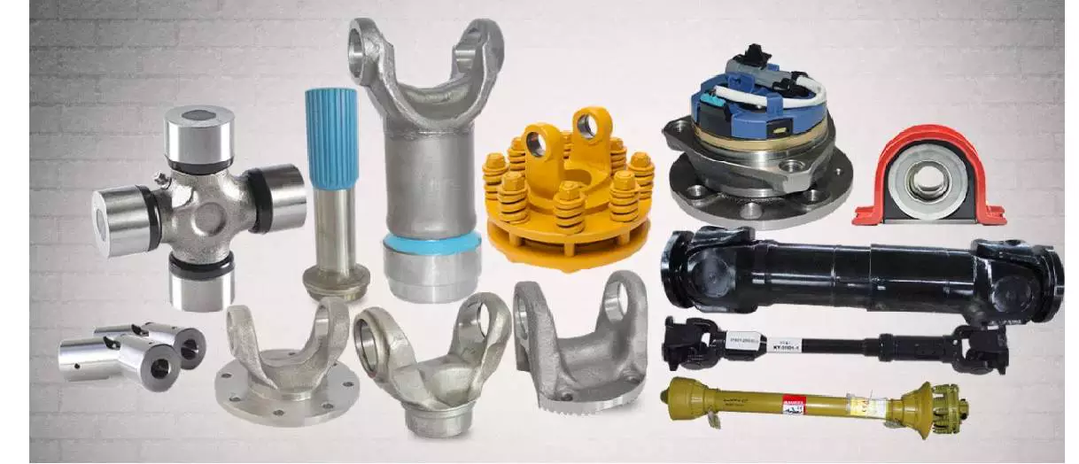
Power Take-Off (PTO) Shafts
Power take-off (PTO) shafts are used on many types of machines, including jet aircraft. They are typically semi-permanently mounted to a marine or industrial engine, and are powered by a drive shaft. The drive shaft also powers secondary implements and accessories. Depending on the application, accessory drives may also be used in aircraft. There are four main types of PTO units used in jet aircraft.
Power take-off (PTO) shaft
The power take-off (PTO) shaft of a tractor can be controlled to operate in one of two modes: automatic and manual. Automatic mode operates when the PTO shaft starts turning and is automatically engaged when the power lift is raised by actuating the lift lever 9. Manual mode operates when the lift lever is not raised.
The manual mode allows for manual adjustments. A retaining band 12 may be adjusted arcuately about PTO shaft S with an axial center parallel to the axis of the PTO shaft S. The retaining band may be secured by conventional over center clamps. The retaining band 12 may also be adjusted arcuately about pin or bolt 30.
Power take-off (PTO) shaft safety retainers are used to prevent unintended disconnection of the PTO shaft. The safety retainers comprise a stationary openable band that circumscribes the PTO shaft near the connection with driven machinery. The band is preferably offset from the axis of the PTO shaft.
While the PTO shaft is a convenient way to transfer mechanical power to farm implements, there are several inherent hazards associated with using it improperly. Accidental disconnections of the PTO shaft pose a significant risk for the operator. A disconnect can cause the PTO shaft to whip around the driven machinery, potentially causing injury.
Power take-off shaft entanglements can be devastating to the limbs trapped in them, requiring amputation in some cases. In addition to being dangerous, the PTO shafts must be fully guarded to prevent contact with the ground. A farmer must never get too close to an operating PTO shaft to protect their own safety.
Types
There are several different types of PTO shafts available to suit various applications. They can vary in size and number of splines. Each standard has a specific speed range and is designed to fit a variety of implements. For example, there are German and Italian types of PTO shafts.
The type of PTO shaft you choose will determine the maximum load that can be safely transferred. Depending on the type, the rate at which the PTO clutch engages will be different. For example, a lower-density PTO shaft will engage at a slower rate than a higher-density PTO shaft, while a higher-density shaft will be more tolerant of higher loads.
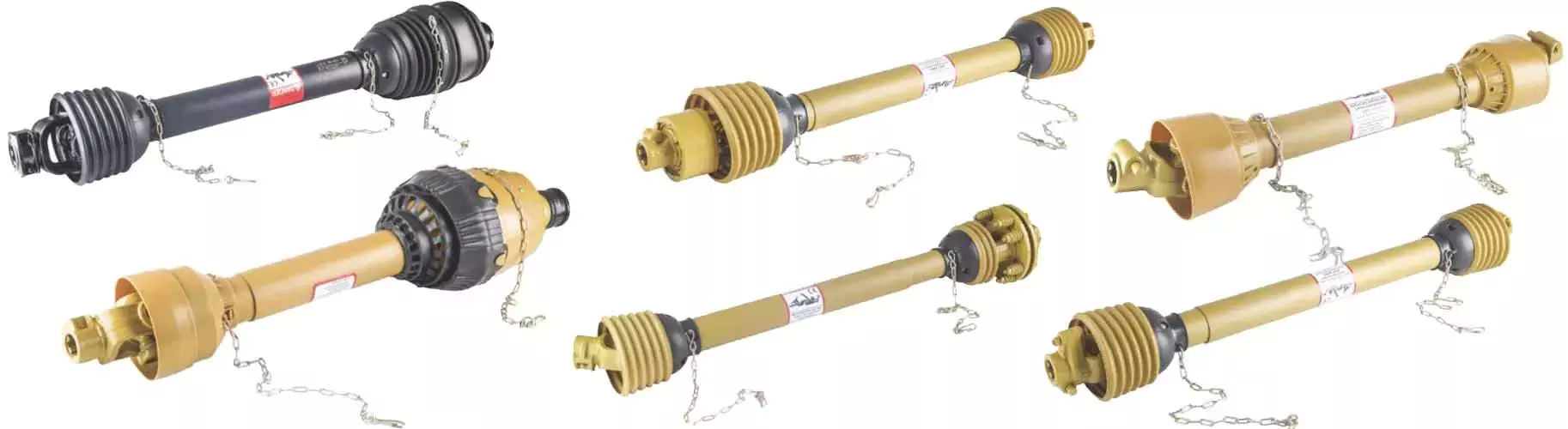
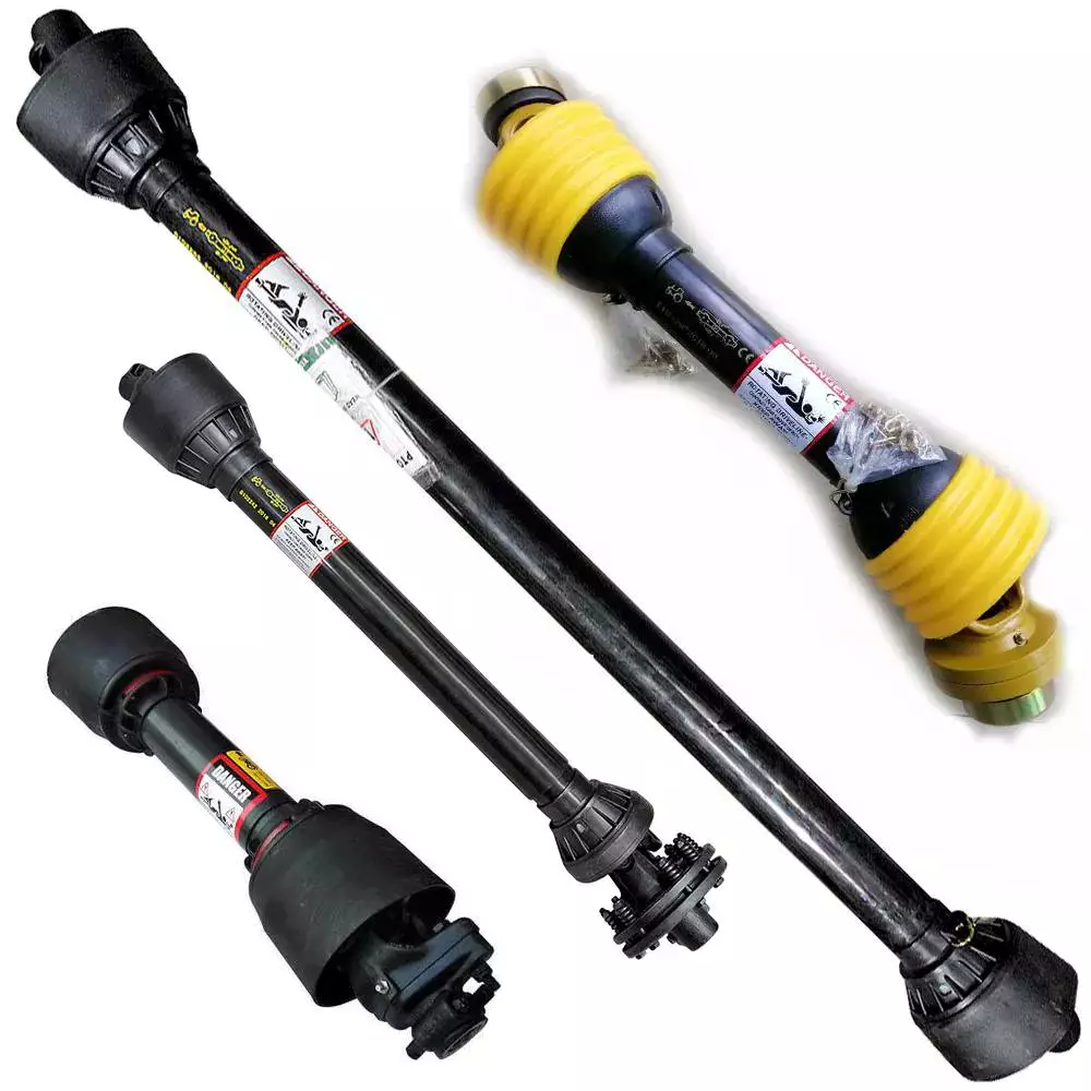
The primary function of a PTO shaft is to secure equipment to the tractor or other agricultural equipment. These parts often feature safety shields on both ends. They are also made in the same shape as the secondary shaft. The front shaft is wider than the secondary shaft, which allows the secondary shaft to fit inside. However, during movement, pieces of the PTO shaft can collapse, making them less safe.
PTO shafts are expensive and easy to steal, so make sure to protect your investment. Make sure the PTO shaft has guards to protect it from thieves. There are two types of PTO shafts: the external and the internal PTO yokes. Internal PTO shafts have an internal PTO yoke, while external PTO shafts use a universal joint. There is also a safety chain and shield on the external PTO shaft.
Depending on the application, you can choose between several different kinds of PTO shafts. Some types of PTO shafts have multiple splines, which can increase the torque transmitted. For applications requiring accuracy and precision, you may want to use a parallel keyed shaft.
Connections
 A PTO shaft has two parts: an input and an output. The input portion of a PTO adapter shaft has a smaller diameter, and the output portion has a larger diameter. Both are connected by splines. These splines have tapered outer ends. The first bore 25 has a first frustoconical wall, while the second bore has a second frustoconical wall.
One of the most common causes of PTO shaft failure is a poorly adjusted clutch. Another common cause is improper lubrication of the PTO shaft’s wide angle joints. PTO shafts should be lubricated at least once every eight hours. If you fail to do this, you risk premature ware and reduced life expectancy.
When a PTO shaft is installed in a tractor, the tractor must be connected to the implement using a coupler frame. The coupler frame has a PTO adapter mounting flange that engages with the PTO stub shaft. The coupler frame can move to accommodate the PTO adapter shaft, and the PTO adapter shaft can pivot and slide with the coupler frame.
When a PTO shaft fails, it can result in damage to the tractor and implement. Identifying the cause will help you fix the problem. Constant compression of the PTO shaft can damage the connecting shafts and connections. This could damage the tractor or implement, resulting in expensive repairs. When this happens, it is important to cut or shorten the shaft to reduce the risk of damage.
PTO shaft 24 extends rearward from tractor 10 and is connected to the front universal joint 28 and first end of variable-length splined drive shaft 32. The shaft is connected to a drive mechanism 36 on a mobile work implement 34. This drive mechanism may be mechanical, hydraulic, or a combination of both.
Safety
It is very important for every person using a tractor to understand the safety of PTO shafts. PTOs can be extremely dangerous, and without the correct shielding, they can cause serious injury. It can also be very dangerous if someone accidentally steps on or falls on one while the machine is operating. This is why it is important for everyone using a tractor to read the manufacturer’s manual and follow the safety guidelines for PTO shafts. Moreover, PTOs must only be used for the purpose intended.
PTO safety should be the number one priority for every operator. A small child was tragically killed when he became entangled with a spinning PTO shaft. His father tried to pull him out of the shaft, but was unable to do so. His clothing, which was near the spinning shaft, caught on the PTO and dragged him into it. His body was thrown around the shaft several times, and he sustained injuries to his leg, right arm, and head.
The PTO shaft is an important part of a tractor, and is used to secure the equipment. It is usually secured by safety shields on both ends. There are several kinds of safety shields. One type is a shield that is attached to the front of the PTO shaft. Another type is a shield that rotates freely on its bearings.
Power takeoffs are common on most small and compact tractors, construction machinery, and other equipment. They rotate to provide the drive for the equipment. However, the PTO shaft is very dangerous because it can easily catch something that gets too close to it. Moreover, loose items can also get tangled around the PTO shaft.
Maintenance
 One of the most important things to do in order to keep your PTO shaft in top condition is to keep it properly greased. This can be done by using a grease gun or a hand pump. It is important to keep the grease fresh and apply it in the appropriate amounts depending on how much you use the PTO. It is also important to separate the primary and secondary shafts and remove any debris from them.
It is also important to check the spline threads on your PTO on a periodic basis. This is important because some signs of dry shafts are not always immediately apparent. Similarly, spline threading and corrosion can occur behind the scenes and go undetected. Proper PTO maintenance is a vital part of safe and efficient operation.
A damaged or worn drive shaft will prevent your car from turning freely, leaving you exposed to higher repair bills. In addition, it will drastically affect the performance of your car. A broken drive shaft can even result in a crash. You should take your vehicle to a mechanic as soon as you notice any of these problems.
Fortunately, most PTO-driven equipment is equipped with a shear pin to prevent collisions and prevent damage to the gearbox and shaft. It should also be replaced regularly to prevent excessive wear. Long bolts pose a risk of entanglement and can easily catch clothing or gloves. For safety reasons, it is important to disengage the PTO when not in use.
Another thing to do is to keep the PTO shields clean. They must be regularly rotated and tested. Always ensure that your drawbar is properly configured for your machine. This prevents stressing or separating the driveline.

editor by CX 2023-07-13
China high quality agriculture machinery mini farm tractor mounted green machine road snow sweepers for sale agricultural parts direct
Equipment Kind: Flooring Sweeper
Relevant Industries: Producing Plant, Machinery Fix Retailers, Farms, House Use, Building functions
Online video outgoing-inspection: Supplied
Equipment Examination Report: Provided
Warranty of core factors: 1 Yr
Main Components: Bearing, Equipment
Condition: New
Gas: Diesel
Use: Snow Clearning, Sweeping highway, P series Heavy Obligation Mixer Hydraulic Geared Motor Planetary Gearbox Velocity Reducer avenue
Cleansing Process: brush
Cleaning Sort: TRACTOR PTO Pushed Clearning
Substance: Metal / Coil
Energy: 20-150hp
Dimension(L*W*H): 1330mm*900mm*1200mm
Guarantee: 1 Yr
Excess weight (KG): 550 kg
Type: Experience-on, mounted with tractors
Item title: tractor mounted street sweeper
Colour: Underneath Client’s Instruction
Purpose: Sweeping snow, street
functioning width: 1500mmm
Composition bodyweight:: 180kgs
Brush material: PP Blended Steel
brush rotation speed: a hundred and eighty rpm
Driveline specification:: Motor/pto drive
Connecting technique with tractor: 3-point suspension
Packaging Particulars: IRON Bundle
Port: HangZhou PORT
Items Description actor highway sweeper: 1. SX Collection Snow Sweeper for tractor is used for sweeping of thin layer of snow, showcased with fast velocity, higher effectiveness andeasy procedure. To distinct away deep snow, it will be far more successful to use it with each other with snow blade. It is also used in sweepingon street and floor.2. SX Series Snow Sweeper for tractor is commonly employed in highway, Custom Substantial Quality Agriculture Equipment Tractor Elements Driveline Cardan Drive PTO Shaft ground, warehouse and so forth, mostly in sweeping of skinny layer of snow,leaves, sand, courtroom and so forth.3.The snow sweeper can be matched to tractor,wheel loader, Stober K514SG3000EK501U Gear Head Velocity Reducers forklift,4.The snow sweeper driven by hydraulic output of these equipment,only tractor could be pushed by PTO.5.PP with metal wires brushes.6.Working width from 1200 to 2500mm7.Suited for cleansing highway,avenue,floor and other flat. Product Technical specs
| Model | SX-150 | SX-one hundred sixty five | SX-a hundred and eighty | SX-210 | ||
| Matching tractor | 20-40hp | 40-60hp | 70-80hp | 85hp-120hp | ||
| Hoisting device | 3-stage | |||||
| Sweeping width (mm) | 1500 | 1650 | 1800 | 2100 | ||
| Brush roller length(mm) | 1740 | 1910 | 2100 | 2450 | ||
| Sweeping thickness(mm) | 0~60 | 0~60 | 0~60 | 0~60 | ||
| Sweeping speed (km/h) | 5~15 | 5~15 | 5~15 | 0~60 | ||
| Brush roller diameter(mm) | 500 | 500 | 500 | 5~15 | ||
| Sweeping angle | 30° | 30° | 30° K37 helical bevel gear motor 3 phase motor pace reducer gearbox large torque pace reducer gearbox | 500 | ||
| Max. transportation height(mm) | 500 | 550 | 600 | 30° | ||
Calculating the Deflection of a Worm Shaft
In this article, we’ll discuss how to calculate the deflection of a worm gear’s worm shaft. We’ll also discuss the characteristics of a worm gear, including its tooth forces. And we’ll cover the important characteristics of a worm gear. Read on to learn more! Here are some things to consider before purchasing a worm gear. We hope you enjoy learning! After reading this article, you’ll be well-equipped to choose a worm gear to match your needs.
Calculation of worm shaft deflection
The main goal of the calculations is to determine the deflection of a worm. Worms are used to turn gears and mechanical devices. This type of transmission uses a worm. The worm diameter and the number of teeth are inputted into the calculation gradually. Then, a table with proper solutions is shown on the screen. After completing the table, you can then move on to the main calculation. You can change the strength parameters as well.
The maximum worm shaft deflection is calculated using the finite element method (FEM). The model has many parameters, including the size of the elements and boundary conditions. The results from these simulations are compared to the corresponding analytical values to calculate the maximum deflection. The result is a table that displays the maximum worm shaft deflection. The tables can be downloaded below. You can also find more information about the different deflection formulas and their applications.
The calculation method used by DIN EN 10084 is based on the hardened cemented worm of 16MnCr5. Then, you can use DIN EN 10084 (CuSn12Ni2-C-GZ) and DIN EN 1982 (CuAl10Fe5Ne5-C-GZ). Then, you can enter the worm face width, either manually or using the auto-suggest option.
Common methods for the calculation of worm shaft deflection provide a good approximation of deflection but do not account for geometric modifications on the worm. While Norgauer’s 2021 approach addresses these issues, it fails to account for the helical winding of the worm teeth and overestimates the stiffening effect of gearing. More sophisticated approaches are required for the efficient design of thin worm shafts.
Worm gears have a low noise and vibration compared to other types of mechanical devices. However, worm gears are often limited by the amount of wear that occurs on the softer worm wheel. Worm shaft deflection is a significant influencing factor for noise and wear. The calculation method for worm gear deflection is available in ISO/TR 14521, DIN 3996, and AGMA 6022.
The worm gear can be designed with a precise transmission ratio. The calculation involves dividing the transmission ratio between more stages in a gearbox. Power transmission input parameters affect the gearing properties, as well as the material of the worm/gear. To achieve a better efficiency, the worm/gear material should match the conditions that are to be experienced. The worm gear can be a self-locking transmission.
The worm gearbox contains several machine elements. The main contributors to the total power loss are the axial loads and bearing losses on the worm shaft. Hence, different bearing configurations are studied. One type includes locating/non-locating bearing arrangements. The other is tapered roller bearings. The worm gear drives are considered when locating versus non-locating bearings. The analysis of worm gear drives is also an investigation of the X-arrangement and four-point contact bearings.
Influence of tooth forces on bending stiffness of a worm gear
The bending stiffness of a worm gear is dependent on tooth forces. Tooth forces increase as the power density increases, but this also leads to increased worm shaft deflection. The resulting deflection can affect efficiency, wear load capacity, and NVH behavior. Continuous improvements in bronze materials, lubricants, and manufacturing quality have enabled worm gear manufacturers to produce increasingly high power densities.
Standardized calculation methods take into account the supporting effect of the toothing on the worm shaft. However, overhung worm gears are not included in the calculation. In addition, the toothing area is not taken into account unless the shaft is designed next to the worm gear. Similarly, the root diameter is treated as the equivalent bending diameter, but this ignores the supporting effect of the worm toothing.
A generalized formula is provided to estimate the STE contribution to vibratory excitation. The results are applicable to any gear with a meshing pattern. It is recommended that engineers test different meshing methods to obtain more accurate results. One way to test tooth-meshing surfaces is to use a finite element stress and mesh subprogram. This software will measure tooth-bending stresses under dynamic loads.
The effect of tooth-brushing and lubricant on bending stiffness can be achieved by increasing the pressure angle of the worm pair. This can reduce tooth bending stresses in the worm gear. A further method is to add a load-loaded tooth-contact analysis (CCTA). This is also used to analyze mismatched ZC1 worm drive. The results obtained with the technique have been widely applied to various types of gearing.
In this study, we found that the ring gear’s bending stiffness is highly influenced by the teeth. The chamfered root of the ring gear is larger than the slot width. Thus, the ring gear’s bending stiffness varies with its tooth width, which increases with the ring wall thickness. Furthermore, a variation in the ring wall thickness of the worm gear causes a greater deviation from the design specification.
To understand the impact of the teeth on the bending stiffness of a worm gear, it is important to know the root shape. Involute teeth are susceptible to bending stress and can break under extreme conditions. A tooth-breakage analysis can control this by determining the root shape and the bending stiffness. The optimization of the root shape directly on the final gear minimizes the bending stress in the involute teeth.
The influence of tooth forces on the bending stiffness of a worm gear was investigated using the CZPT Spiral Bevel Gear Test Facility. In this study, multiple teeth of a spiral bevel pinion were instrumented with strain gages and tested at speeds ranging from static to 14400 RPM. The tests were performed with power levels as high as 540 kW. The results obtained were compared with the analysis of a three-dimensional finite element model.
Characteristics of worm gears
Worm gears are unique types of gears. They feature a variety of characteristics and applications. This article will examine the characteristics and benefits of worm gears. Then, we’ll examine the common applications of worm gears. Let’s take a look! Before we dive in to worm gears, let’s review their capabilities. Hopefully, you’ll see how versatile these gears are.
A worm gear can achieve massive reduction ratios with little effort. By adding circumference to the wheel, the worm can greatly increase its torque and decrease its speed. Conventional gearsets require multiple reductions to achieve the same reduction ratio. Worm gears have fewer moving parts, so there are fewer places for failure. However, they can’t reverse the direction of power. This is because the friction between the worm and wheel makes it impossible to move the worm backwards.
Worm gears are widely used in elevators, hoists, and lifts. They are particularly useful in applications where stopping speed is critical. They can be incorporated with smaller brakes to ensure safety, but shouldn’t be relied upon as a primary braking system. Generally, they are self-locking, so they are a good choice for many applications. They also have many benefits, including increased efficiency and safety.
Worm gears are designed to achieve a specific reduction ratio. They are typically arranged between the input and output shafts of a motor and a load. The two shafts are often positioned at an angle that ensures proper alignment. Worm gear gears have a center spacing of a frame size. The center spacing of the gear and worm shaft determines the axial pitch. For instance, if the gearsets are set at a radial distance, a smaller outer diameter is necessary.
Worm gears’ sliding contact reduces efficiency. But it also ensures quiet operation. The sliding action limits the efficiency of worm gears to 30% to 50%. A few techniques are introduced herein to minimize friction and to produce good entrance and exit gaps. You’ll soon see why they’re such a versatile choice for your needs! So, if you’re considering purchasing a worm gear, make sure you read this article to learn more about its characteristics!
An embodiment of a worm gear is described in FIGS. 19 and 20. An alternate embodiment of the system uses a single motor and a single worm 153. The worm 153 turns a gear which drives an arm 152. The arm 152, in turn, moves the lens/mirr assembly 10 by varying the elevation angle. The motor control unit 114 then tracks the elevation angle of the lens/mirr assembly 10 in relation to the reference position.
The worm wheel and worm are both made of metal. However, the brass worm and wheel are made of brass, which is a yellow metal. Their lubricant selections are more flexible, but they’re limited by additive restrictions due to their yellow metal. Plastic on metal worm gears are generally found in light load applications. The lubricant used depends on the type of plastic, as many types of plastics react to hydrocarbons found in regular lubricant. For this reason, you need a non-reactive lubricant.
