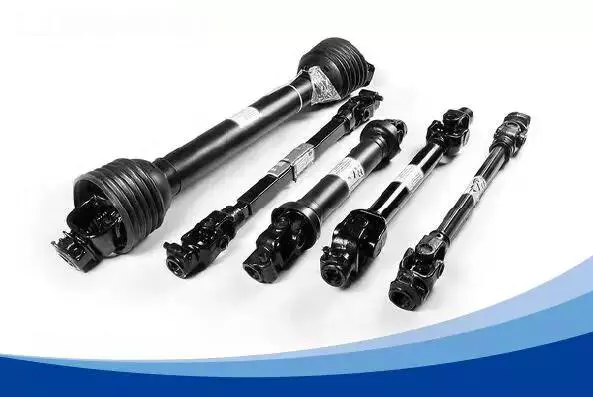
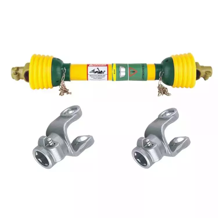
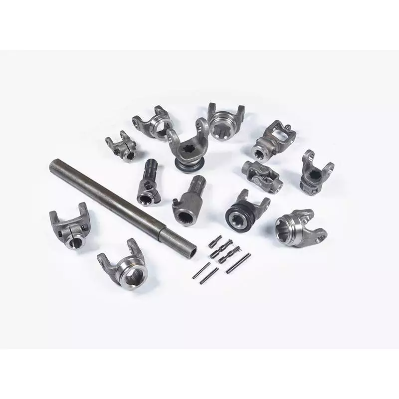
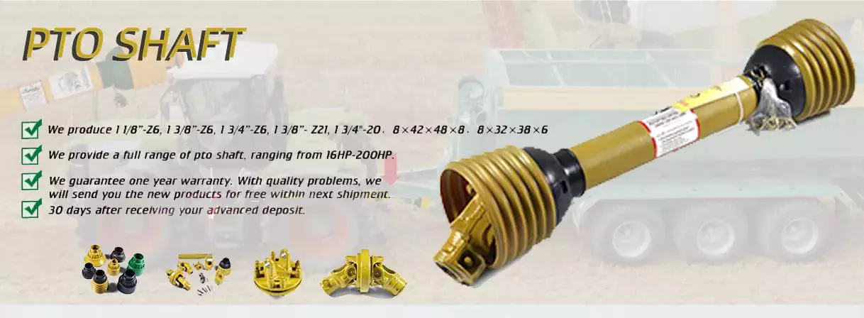
Tag Archives: attaching pto shaft to tractor

China agricultural transmission bronze big square pto output drive gearbox hollow spline shafts screw input rotor main wheel shaft attaching pto shaft to tractor

Problem: New
Warranty: 3 months
Relevant Industries: Building Content Retailers, Manufacturing Plant, Machinery Repair Retailers, Foodstuff & Beverage Manufacturing facility, Farms, Restaurant, Meals Store, Printing Stores, Vitality & Mining, Other
Weight (KG): 6 KG
Showroom Spot: None
Online video outgoing-inspection: Presented
Machinery Examination Report: Presented
Marketing Type: Regular Item
Packaging Particulars: Neutral paper packaging, wooden packing containers for outer box or according to customer’s demand.
Port: ZheJiang / HangZhou

agricultural transmission bronze huge square pto output travel gearbox hollow spline shafts screw enter rotor principal wheel shaft
:
(1). All types of gears, shaft, equipment shaft, precision gear and CNC equipment. (2). Specialized in manufacturing all types of vehicle transmission element primarily based on drawings (3). Content: ductile solid iron, carbon steel, MY1016 DC 24v 250w electric wheelchair motor with electromagnetic brake 75rpm 120rpm 160rpm mobility motor vehicle garden mower dc motor alloy steel , stainless steel, , bronze/brass (4). Modules: M1 to M8 (5). Fulfills ISO, DIN and ASTM specifications (6). Specification : In accordance to the the drawing
(7). Certification: ISO/TS16949:2009

Material
Carbon Steel
SAE1571, SAE1045, Cr12, 40Cr, Y15Pb, 1214Letc
Alloy Steel
20CrMnTi, 16MnCr5, 20CrMnMo, 41CrMo, 17CrNiMo5etc
Brass/Bronze
HPb59-1, H70, Rolling Shutter Quick Pvc Higher Velocity Rolling Door POWEVER A4-PE200 1.5KW Handle Box and Motor CuZn39Pb2, CuZn40Pb2, C38000, CuZn40etc
Tolerance Handle
Outer Diameter
Based on drawing
Size Dimension
Based mostly on drawing
Machining Procedure
Gear Hobbing, Gear Milling, Equipment Shaping, Equipment Broaching, Gear Shaving, Equipment Grinding and Equipment Lapping
Enamel Accuracy
DIN Class 4, ISO/GB Course 4, AGMA Class 13, JIS Class
Modules
1., 1.25, 1.5, 1.75, 220V US-fifty two 6W solitary stage ac motor speed controller for YN60-6 2., 2.twenty five, 2.5….8. and so on
Warmth Remedy
Quenching & Tempering, Carburizing & Quenching, High-frequency Hardening, Carbonitriding
Floor Treatment
Blacking, Sharpening, Anodization, Chrome Plating, Zinc Plating, Nickel Plating
Common
1. DIN, ISO/GB, AGMA, 60V72V96V vector sine wave clever brushless DC motor controller is suited for massive motorbike electric vehicle drive JIS,IATF16949:2016

drive shaft electric motor
China agricultural transmission bronze big square pto output drive gearbox hollow spline shafts screw input rotor main wheel shaft     attaching pto shaft to tractorChina agricultural transmission bronze big square pto output drive gearbox hollow spline shafts screw input rotor main wheel shaft     attaching pto shaft to tractor
editor by Cx 2023-06-29

China Good quality OEM ODM Cardan Transmission Tractor Parts Pto Drive Shaft for Agriculture Machinery with CE Certificate attaching pto shaft to tractor

Product Description

Company Profile

Certifications

Exhibition Strength


Our Advantages

FAQ

Q: Are you trading company or manufacturer ?
A: We are exactly a factory.

Q: Do you provide samples ? is it free or extra ?
A: Yes, we could offer the sample for free charge but do not pay the cost of freight.

Q: How long is your delivery time ? What is your terms of payment ?
A: Generally it is 40-45 days. The time may vary depending on the product and the level of customization. For standard products,
the payment is: 30% T/T in advance, balance before shippment.

Q: What is the exact MOQ or price for your product ?
A: As an OEM company, we can provide and adapt our products to a wide range of needs.Thus, MOQ and price may greatly vary with
size, material and further specifications; For instance, costly products or standard products will usually have a lower MOQ.


 Any questions are welcomed! Come and contact us !


Shipping Cost:

Estimated freight per unit.


To be negotiated
Service: OEM/ODM
Certificate: ISO9001
Transport Package: Standard Marine Wooden Case
Samples:
US$ 999999/Piece
1 Piece(Min.Order)

|

Order Sample

Customization:
Available

|

Customized Request

Shaft Collar

PTO Shafts and PTO Shaft Shields

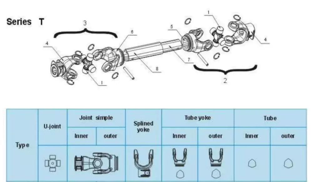
When choosing a PTO shaft, measuring the various pieces is an important aspect. Each piece must be measured in a specific way, with the shaft in a closed position. Measure the length between the outsides of the yokes. The closed length will help you determine the correct PTO series size for the horsepower of your tractor.

540 rpm

A 540 RPM PTO Shaft will fit CZPT PTO models. These shafts are slightly indexed to allow for easy PTO drive hookups. These shafts will also work with 1000 RPM implements. They also feature a snap ring that will allow for quick and easy removal.
PTO shafts are commonly divided into two types: 1000 RPM and 540 RPM. The 540 RPM PTO shafts are smaller, with only six splines, while the 1000 RPM PTO shafts are larger. The 540 RPM version is used with implements that require less horsepower and are made for light-duty use.
The PTO shaft transfers power from the tractor’s engine to a PTO-driven implement. When operating at its recommended speed, the PTO shaft rotates at 540 rpm (9 times per second). The higher speed PTO shafts have more splines.

Safety chains

Safety chains for PTO shafts are an important safety feature to consider when operating a tractor. These chains are welded to the drive end of a tractor or implement. They are used to prevent the plastic shield from spinning on the PTO shaft. The chain’s reaction time is slower than the speed of the PTO shaft, which makes it important for safety.
When operating a tractor, it is important to follow the manufacturer’s instructions and keep the machine and equipment in a safe location. A poorly-guarded PTO can entrap ground personnel or cause a serious accident. Operator awareness is also important. It is important to avoid stepping over a revolving shaft, wearing loose clothing, or making repairs while the tractor is running. It is also important to follow the manufacturer’s instructions and use the PTO for its intended purpose.
The safety chains for PTO shafts must be properly connected and fully functional before each use. During a PTO operation, the PTO shaft may rotate as much as 1000 rpm, which is potentially deadly. In addition to safety chains, the tractor should have a clutch or torque limiter fitted on the implement end.
The PTO shaft must have a correct length for the machine. If it is a sliding metal PTO drive shaft, it is important to lubricate it according to manufacturer’s specifications. Lubrication is recommended after every eight hours of operation. Also, make sure that the button on the end of the PTO shaft moves freely. Hammering it into place can damage the guard and the shaft.
A PTO driveline hazard is one of the oldest farm machinery hazards. It refers to the PTO or Implement Input Connection. There are often protruding pins and bolts on the driveline, which can snag clothing.

Shield

Shaft CollarThe PTO shaft shield is a protective piece that encloses a PTO shaft. These shields are usually plastic, but some are also made of metal. They are made to protect the PTO shaft from debris, which can cause premature wear and damage to the universal joints. A PTO shaft shield is not a permanent fixture, but can be easily removed for replacement or repair.
The PTO shaft shield should be checked periodically to ensure that it is in good condition. It should have no loose ends or loose bolts. Ensure that the shear bolts and pins are the right length and hardness for the PTO shaft. Additionally, the operator should wear snug clothing to avoid stepping on the PTO shaft while working.
The PTO shaft shield should fit snugly over the PTO shaft. If the PTO shaft is loose, it may be difficult to attach the safety shield. However, with a proper PTO shaft shield, the process should be quick and easy. A CZPT safety clip allows easy removal and prevents co-rotation between the inner driveshaft and the safety shield. The driveline safety shield from RPM Transmissions is made of CZPT, which is a rigid and durable material.
In addition, some machine drive shafts are lacking a shield. This can cause a safety hazard. Without a PTO shaft shield, an operator may accidentally touch the shaft and get injured. These guards prevent this danger by enclosing the shaft in a plastic or metal guard.
The PTO shaft shield is a crucial part of tractor safety. It helps protect the operator from accidental entanglement while operating the tractor. When the PTO shaft stub becomes separated, it can cause severe injuries and even fatalities. Thankfully, the industry has made tremendous progress in reducing the risks associated with PTO mishaps. Operators must make sure they maintain the shields and do not remove them if not in use.

Reverse rotation

Shaft CollarThe PTO shaft reverse rotation mechanism prevents the main drive shaft from moving in a direction opposite to the direction of rotation of the driven shaft. The mechanism is compact, reducing the length of the rotation shaft. The mechanism includes two reversing members: first reversing member 151 rotates in a clockwise direction and second reversing member 153 rotates in a counterclockwise direction.
In a PTO shaft reverse rotation mechanism, a driven shaft is inserted into a hollow cylindrical body. It is rotatably positioned relative to the main driving shaft 112 and radially symmetrically around it. As a result, the driving and reverse-rotation mechanisms are symmetric.
One such PTO shaft reverse rotation mechanism has a main drive shaft and a driven shaft, and a plurality of transmission units coupled to it. The driven shaft and the transmission member rotate in tandem. The transmission units are arranged radially about the main driving member and the driven shaft. Alternatively, one of the reversing units may comprise the second reversing member and the first driving member.
China Good quality OEM ODM Cardan Transmission Tractor Parts Pto Drive Shaft for Agriculture Machinery with CE Certificate   attaching pto shaft to tractorChina Good quality OEM ODM Cardan Transmission Tractor Parts Pto Drive Shaft for Agriculture Machinery with CE Certificate   attaching pto shaft to tractor
editor by CX 2023-05-10

China Anon Agriculturel Equipment Multi-Purpose Agricultural Corn Thresher Household Thresher attaching pto shaft to tractor

Product Description

Anon Agriculturel Equipment Multi-Goal Agricultural Corn Thresher House Thresher

Introduction CZPT Agriculturel Tools Multi-Function Agricultural Corn Thresher home thresher:
5T-a thousand multi CZPT thresher, utilised for corn, sorghum, millet, castor,soybean and so forth. It can be driven by 11kw electrical motor or 12hp diesel motor or tractor PTO. With really very good effect and massive capability. Each established thresher send alongside with 3 pcs screen for various crop.
 

Design 5T-1000
Dimension 2460x1400x1900mm
Roller size 1000mm
Threshing corn hammer 48pcs
Threshing sorghum millet soybeans enamel 36pcs
Capability 3000kg/h for corn, one thousand-2000kg for millet sorghum, four hundred-600kg/h for beans, grain moisture content 15-20 %
Primary shaft speed 650-700rpm
Cleaning strategy Vibration display screen separation + admirer cleaning
Matched electricity 7.5-11kw electric powered motor or >12hp diesel engine or tractor PTO
Device bodyweight 400-600kg with various configuration,exclude electrical power
Colour Crimson/Green


Type: Maize Threshing Machine
Application: Rice, Corn, Wheat, Soybean
Power Source: Diesel
Harvest method: Maize Threshing Machine
Drive Type: Vee belt
Transmission: Soft Shaft

###

Model 5T-1000
Size 2460x1400x1900mm
Roller length 1000mm
Threshing corn hammer 48pcs
Threshing sorghum millet soybeans teeth 36pcs
Capacity 3000kg/h for corn, 1000-2000kg for millet sorghum, 400-600kg/h for beans, grain moisture content 15-20 %
Main shaft speed 650-700rpm
Cleaning method Vibration screen separation + fan cleaning
Matched power 7.5-11kw electric motor or >12hp diesel engine or tractor PTO
Machine weight 400-600kg with different configuration,exclude power
Color Red/Green

What Is a PTO Shaft?

A PTO shaft is a component that is important for a power take-off (PTO) tractor. There are many different kinds of PTOs, including Italian, German, and North American types. The types are categorized into different series, which will have different features such as bearing diameter, cap-to-cap length, and snap rings.
Shaft Collar

Power Take-Off (PTO) shaft

A PTO shaft is a high-speed working shaft that provides torque and lift. This is an advantage for machines that lift and lower loads and are often used on construction sites. Often, the operating elements are located outside of the operator’s cabin. A safety system is also present that allows the PTO shaft to automatically disengage if it is not turned on.
A safety retaining band 12 is used to secure the PTO shaft. The retaining band extends axially from the PTO shaft S and includes a hinge. The band may be adjustable in width to ensure a correct clearance from the PTO shaft. If necessary, it may also be secured with a conventional over-center clamp.
The power-take-off (PTO) shaft is a crucial part of a tractor. Understanding how power is transferred from the tractor’s engine to the implement requires a better understanding of how this shaft works. The torque and speed of the PTO shaft is essential to developing and utilizing the power of the tractor. There are many ways to measure torque and speed at the PTO shaft, including using a telemetry or encoder system.
A Power Take-Off (PTO) shaft safety retainer is an inexpensive, dependable, and fully effective device that protects the PTO shaft from entanglement. Its effectiveness will become clear after reading the specification. A power take-off shaft safety retainer is not difficult to install and is a good choice for many applications.
PTO shafts have a dangerous tendency to separate from the driven machinery. This poses a safety hazard because the PTO shaft can continue to whip around while the operator is driving the machine. Additionally, it can be very difficult for the operator to reach the power plant when operating PTO-driven equipment.

Safety chain

The safety chain on your PTO shaft is an important component of your tractor’s safety system. A properly guarded PTO can prevent entanglement with people, tools, and objects. Moreover, it reduces the risk of the PTO shaft becoming detached from the tractor. It also prevents people from stepping over the rotating shaft.
When not guarded, a PTO shaft is extremely dangerous. It can cause serious injuries and even death. Proper safety chains can prevent this from happening and protect livestock from damage to the PTO shaft. If you’re looking to purchase a safety chain for your PTO shaft, be sure to get one that fits tightly.
When properly attached, a safety chain can keep the shaft from swinging when the PTO is engaged. A 540-rpm PTO shaft will make more than two complete revolutions in less than five seconds. That means it can wrap someone in five tenths of a second. And if you try to pull away, you’ll get wrapped even tighter!
Another reason to use a safety chain is to prevent injury from clothing getting caught in the drive shaft. A jacket or a sweater can entangle itself around the PTO shaft and cause a serious injury. The clothing can also trap the injured limb against the shaft. Hence, the chain should be removed as soon as possible after the operation is completed.
A safety chain is an essential part of your tractor’s safety system. It prevents an accident from happening because of improper maintenance. A poorly maintained PTO shaft can result in severe injuries or even death. Properly installed and maintained safety chain can help you prevent any kind of PTO shaft accident.
Shaft Collar

Universal joint

A bad universal joint can cause a number of problems for your tractor or implement. These issues may include squeaking or clunking noises when you shift gears, or a shuddering sensation when you brake. If you notice any of these symptoms, it is best to take your vehicle to a mechanic right away for a thorough inspection. If not fixed properly, a bad universal joint can separate from the drive shaft and cause major damage to the tractor or implement.
In order to choose the proper universal joint, you must consider the size of your PTO shaft. Some implements have a diameter of 14 inches or more from the hitch point to the end of the input shaft. The longer distance helps prevent the PTO shaft from bottoming out when making sharp turns. It also prevents the two parts of the shaft from detaching during cornering.
Universal joints are used in agricultural and forestry equipment and other vehicles with large number of rotors. They can be made of different materials. The most common is steel or stainless steel. This material can last for many years. A universal joint is an excellent option for small tractors, lawn mowers, and other agricultural equipment.
The universal joint is also very useful when coupling or extending drive lines. It comes with 2 yokes and a cross kit. The yokes measure 6 x 13/8″ spline, while the cross kit measures 30,2 x 92 mm. The universal joint is made to withstand extreme temperatures. It can be easily disassembled and serviced if necessary.

Square rigid shaft

Torsion is a property of a mechanical system that is affected by changes in torsional rigidity. Torsional rigidity is measured as the torque needed to twist one unit of angular measurement over one unit of length. A shaft with high torsional rigidity will provide a stable mechanical interface.
Different shafts may have different types of collars. The most basic one is a sleeve, which is composed of a thick tube with the same diameter as the shaft. The sleeve is attached to each end of the shaft and has threaded inserts to prevent longitudinal movement.
The PTO shaft also has a safety shield on both ends. It helps to prevent accidents by securing equipment to the tractor. It can be found in domestic and metric shapes. The domestic versions are generally round and domestic shaped, while metric versions are available in a bell, football, star, and metric shape.
An CZPT coupling consists of three pieces: a center plastic disc, two encompassing discs, and a flange. These parts are joined together with a ring that is screwed to the shaft. Some couplings feature oil injection points on the coupling. These can supply oil under pressure to the coupling’s annular grooves. This helps it ‘float’ and aids in the removal.
Another type of flexible coupling is the universal joint. These couplings can be made from a variety of materials, such as rubber, braided metal wire, or woven wire. They can be fabricated to withstand various misalignments. But, unlike rigid couplings, flexible couplings are susceptible to shock and vibration.
Shaft Collar

Economy PTO

Economy PTO shafts are designed to reduce the overall torque and power consumption of a tractor. They can be manually adjusted to engage and disengage the PTO. The cab mounted control/monitoring unit 14 has a switch 19 that selects between the economy and normal driving modes of the PTO. Using the economy mode decreases the engine rpm while using a lower gear ratio to drive the PTO shaft.
Economy PTO shafts come in hydraulic and mechanical versions. Both types are suitable for agricultural tractors. They allow the tractor to operate at a lower rpm, which reduces noise and vibration. They can also be used in a wide range of equipment. The transmission PTO is the oldest type, and is directly connected to the transmission. When the clutch is engaged, it drives the transmission.
Standard PTO shafts are available in various diameters, splines, and speeds. Many implements are designed to be compatible with one or more of these types of PTO shafts. The domestic versions come with a splined front shaft and a square, rectangle, or round secondary shaft.
Another difference between the two types is the number of teeth on the toothed wheel. The economy PTO allows the tractor to run at a lower rpm than the standard PTO. The engine rpm can go as low as 1600 while using the economy PTO. It also helps to reduce noise and vibration in the cab.
The present invention solves these issues and provides an increased level of automation and operator awareness of the PTO function. It also includes a system for detecting the type of PTO shaft and automatically setting the parameters of the control routine.
China Anon Agriculturel Equipment Multi-Purpose Agricultural Corn Thresher Household Thresher     attaching pto shaft to tractorChina Anon Agriculturel Equipment Multi-Purpose Agricultural Corn Thresher Household Thresher     attaching pto shaft to tractor
editor by CX 2023-04-03

China Carbon Steel 14 2 34 PTO Shaft Locking Pin Heavy Duty Square Wire Lock Pin for Farm Trailers attaching pto shaft to tractor

Design Amount: 1/4
Variety: Sq.
Finish: Bright(Uncoated)
Name: Square sort wire lock pin
Pin Sort: PTO pins for farm trailers
Diameter: 1/four
Pin duration: 2 3/4
Operate size: 2 23/64
Wire variety: double wire
Substance: Carbon steel zinc plated
MOQ: 3000PCS
Shipping and delivery time: 7-fifteen times
Quality: A2
Packaging Specifics: Regular Export Packing Technique, bulk packing,25~30kgs/CTN,then pallet packed cartons packed only if much less than 250KGS
Port: HangZhou or ZheJiang

Carbon Steel 1/4″ 2 3/4″ PTO Shaft Locking Pin Heavy Duty Square Wire Lock Pin for Farm Trailers Products Description Basic safety Pin, we also can contact it Lock Pin,Detent Pin,Hitch Pin.Goods are generally employed in fields these kinds of as cabinets, electrical appliances, machinery, custom made factory 95w AC brushless solitary section Asynchronous induction electric powered chain noticed sharpener motor cranes, and shipbuilding industries.Commonly utilized materials are stainless metal collection, carbon metal sequence and zinc alloy sequence.We can source numerous kinds of basic safety pins: Double Wire D tab Pins Solitary Wire D tab PinsDouble Wire Square tab Pin O sort Pins,ectAccept personalized security pin, welcome to seek advice from us.

Name:Square Shape Wire Lock Pin
Material:carbon metal
Pin Diameter:1/4″
Length:two 3/4″
Work Size:2 23/sixty four”
Item Paramenters Specifics Photos Offer A lot of Sorts OF CLEVIS PINSWELCOME TO Seek the advice of US OTHER Type,Measurement, 2.5HP magnet dc treadmill motor Material AND Cost Packing and Shipping FAQ Q: what types of pins can you give?A: .We supply various types of pins, this kind of as spring pin, clevis pin, protection pin, swift release pin and inHangZhou plungers.Q: In which are these pins typically employed?A: .Different varieties of pins have different purposes. For example, clevis pin can link and spring pin can repair it.Q: If i want to buy the pin, what measurement should i supply?A: It is dependent on what variety of pin do you want, you can refer to the drawings in our item details.Q: How lengthy is your delivery time?A: We have large inventory, 3 days for stock things,7-15days for manufacturing. Q: Do you supply samples? Is it cost-free or need further costs ?A: Typically demand USD50-USD100. Mildew price is needed for tailored item. Q: What is your terms of payment ?A: fifty% in advance ,50% ahead of shipping and delivery. a hundred% in advance if significantly less than USD5000. Q: What is actually your cost conditions ?A: EXW/FOB/CIF/CFR/FCA/CPT/CIP/DAP/DDPQ: What’ 7P138-63310 CZPT KRL160 KRM180D RX220 rotary tiller CZPT spare areas PTO U-JONIT SHAFT for sale s your product range?A: Our product selection includes a variety of varieties of pins and machined elements.

differential drive shaft
China Carbon Steel 14 2 34 PTO Shaft Locking Pin Heavy Duty Square Wire Lock Pin for Farm Trailers     attaching pto shaft to tractorChina Carbon Steel 14 2 34 PTO Shaft Locking Pin Heavy Duty Square Wire Lock Pin for Farm Trailers     attaching pto shaft to tractor
editor by czh 2023-02-20

China best Propeller shaft / Drive shaft VOLVO attaching pto shaft to tractor

Content: Steel
Type: Travel Shafts
Merchandise name: Drive Shaft Weld Yoke
Packaging Details: 1 plastic bag + 1 cartonor packing in accordance to customer’s requirement.
Port: HangZhou / HangZhou / ZheJiang / HangZhou PORT

CZPT Drive SHAFT
Packaging & Shipping
Our Companies Clients can offer samples or drawings , processing customized.

Analytical Approaches to Estimating Contact Pressures in Spline Couplings

A spline coupling is a type of mechanical connection between two rotating shafts. It consists of two parts – a coupler and a coupling. Both parts have teeth which engage and transfer loads. However, spline couplings are typically over-dimensioned, which makes them susceptible to fatigue and static behavior. Wear phenomena can also cause the coupling to fail. For this reason, proper spline coupling design is essential for achieving optimum performance.
splineshaft

Modeling a spline coupling

Spline couplings are becoming increasingly popular in the aerospace industry, but they operate in a slightly misaligned state, causing both vibrations and damage to the contact surfaces. To solve this problem, this article offers analytical approaches for estimating the contact pressures in a spline coupling. Specifically, this article compares analytical approaches with pure numerical approaches to demonstrate the benefits of an analytical approach.
To model a spline coupling, first you create the knowledge base for the spline coupling. The knowledge base includes a large number of possible specification values, which are related to each other. If you modify one specification, it may lead to a warning for violating another. To make the design valid, you must create a spline coupling model that meets the specified specification values.
After you have modeled the geometry, you must enter the contact pressures of the two spline couplings. Then, you need to determine the position of the pitch circle of the spline. In Figure 2, the centre of the male coupling is superposed to that of the female spline. Then, you need to make sure that the alignment meshing distance of the two splines is the same.
Once you have the data you need to create a spline coupling model, you can begin by entering the specifications for the interface design. Once you have this data, you need to choose whether to optimize the internal spline or the external spline. You’ll also need to specify the tooth friction coefficient, which is used to determine the stresses in the spline coupling model 20. You should also enter the pilot clearance, which is the clearance between the tip 186 of a tooth 32 on one spline and the feature on the mating spline.
After you have entered the desired specifications for the external spline, you can enter the parameters for the internal spline. For example, you can enter the outer diameter limit 154 of the major snap 54 and the minor snap 56 of the internal spline. The values of these parameters are displayed in color-coded boxes on the Spline Inputs and Configuration GUI screen 80. Once the parameters are entered, you’ll be presented with a geometric representation of the spline coupling model 20.

Creating a spline coupling model 20

The spline coupling model 20 is created by a product model software program 10. The software validates the spline coupling model against a knowledge base of configuration-dependent specification constraints and relationships. This report is then input to the ANSYS stress analyzer program. It lists the spline coupling model 20’s geometric configurations and specification values for each feature. The spline coupling model 20 is automatically recreated every time the configuration or performance specifications of the spline coupling model 20 are modified.
The spline coupling model 20 can be configured using the product model software program 10. A user specifies the axial length of the spline stack, which may be zero, or a fixed length. The user also enters a radial mating face 148, if any, and selects a pilot clearance specification value of 14.5 degrees or 30 degrees.
A user can then use the mouse 110 to modify the spline coupling model 20. The spline coupling knowledge base contains a large number of possible specification values and the spline coupling design rule. If the user tries to change a spline coupling model, the model will show a warning about a violation of another specification. In some cases, the modification may invalidate the design.
In the spline coupling model 20, the user enters additional performance requirement specifications. The user chooses the locations where maximum torque is transferred for the internal and external splines 38 and 40. The maximum torque transfer location is determined by the attachment configuration of the hardware to the shafts. Once this is selected, the user can click “Next” to save the model. A preview of the spline coupling model 20 is displayed.
The model 20 is a representation of a spline coupling. The spline specifications are entered in the order and arrangement as specified on the spline coupling model 20 GUI screen. Once the spline coupling specifications are entered, the product model software program 10 will incorporate them into the spline coupling model 20. This is the last step in spline coupling model creation.
splineshaft

Analysing a spline coupling model 20

An analysis of a spline coupling model consists of inputting its configuration and performance specifications. These specifications may be generated from another computer program. The product model software program 10 then uses its internal knowledge base of configuration dependent specification relationships and constraints to create a valid three-dimensional parametric model 20. This model contains information describing the number and types of spline teeth 32, snaps 34, and shoulder 36.
When you are analysing a spline coupling, the software program 10 will include default values for various specifications. The spline coupling model 20 comprises an internal spline 38 and an external spline 40. Each of the splines includes its own set of parameters, such as its depth, width, length, and radii. The external spline 40 will also contain its own set of parameters, such as its orientation.
Upon selecting these parameters, the software program will perform various analyses on the spline coupling model 20. The software program 10 calculates the nominal and maximal tooth bearing stresses and fatigue life of a spline coupling. It will also determine the difference in torsional windup between an internal and an external spline. The output file from the analysis will be a report file containing model configuration and specification data. The output file may also be used by other computer programs for further analysis.
Once these parameters are set, the user enters the design criteria for the spline coupling model 20. In this step, the user specifies the locations of maximum torque transfer for both the external and internal spline 38. The maximum torque transfer location depends on the configuration of the hardware attached to the shafts. The user may enter up to four different performance requirement specifications for each spline.
The results of the analysis show that there are two phases of spline coupling. The first phase shows a large increase in stress and vibration. The second phase shows a decline in both stress and vibration levels. The third stage shows a constant meshing force between 300N and 320N. This behavior continues for a longer period of time, until the final stage engages with the surface.
splineshaft

Misalignment of a spline coupling

A study aimed to investigate the position of the resultant contact force in a spline coupling engaging teeth under a steady torque and rotating misalignment. The study used numerical methods based on Finite Element Method (FEM) models. It produced numerical results for nominal conditions and parallel offset misalignment. The study considered two levels of misalignment – 0.02 mm and 0.08 mm – with different loading levels.
The results showed that the misalignment between the splines and rotors causes a change in the meshing force of the spline-rotor coupling system. Its dynamics is governed by the meshing force of splines. The meshing force of a misaligned spline coupling is related to the rotor-spline coupling system parameters, the transmitting torque, and the dynamic vibration displacement.
Despite the lack of precise measurements, the misalignment of splines is a common problem. This problem is compounded by the fact that splines usually feature backlash. This backlash is the result of the misaligned spline. The authors analyzed several splines, varying pitch diameters, and length/diameter ratios.
A spline coupling is a two-dimensional mechanical system, which has positive backlash. The spline coupling is comprised of a hub and shaft, and has tip-to-root clearances that are larger than the backlash. A form-clearance is sufficient to prevent tip-to-root fillet contact. The torque on the splines is transmitted via friction.
When a spline coupling is misaligned, a torque-biased thrust force is generated. In such a situation, the force can exceed the torque, causing the component to lose its alignment. The two-way transmission of torque and thrust is modeled analytically in the present study. The analytical approach provides solutions that can be integrated into the design process. So, the next time you are faced with a misaligned spline coupling problem, make sure to use an analytical approach!
In this study, the spline coupling is analyzed under nominal conditions without a parallel offset misalignment. The stiffness values obtained are the percentage difference between the nominal pitch diameter and load application diameter. Moreover, the maximum percentage difference in the measured pitch diameter is 1.60% under a torque of 5000 N*m. The other parameter, the pitch angle, is taken into consideration in the calculation.

China best Propeller shaft / Drive shaft VOLVO     attaching pto shaft to tractorChina best Propeller shaft / Drive shaft VOLVO     attaching pto shaft to tractor
editor by czh