Product Description
| Size | 260 cm * 120 cm * 135 cm |
| Drive Wheel | 4WD |
| Power | 12(Kw) |
| Specification | 30-50HP |
| Fuel | Gas / Diesel |
| Weight | 680(kg) |
| Tyres sizes | 500-12/650-16 |
| Usage | Farm Tractor, Garden Tractor, Lawn Tractor |
This is part of the certificate, please contact us if you need more!
We can provide customers with customizable packaging, a large number of goods in stock, and a wide choice of freight routes.
Q1: Can I have a sample order?
A1: Yes, we accept sample order to test and check quality.
Q2: Do you have MOQ limit?
A2: Yes, we have MOQ limit for mass production, but it depends on model. Please contact us for details.
Q3: How about the lead time?
A3: Samples will takes 5-7 business days. Mass production will takes 25-30 days. It depends on quantity.
Q4: How about shipping and delivery time?
A4: Generally, Item will be shipped via Express, such as DHL, TNT, FedEx and UPS, delivery time is 3-7 business days. Airline and sea shipping also available.
In order to better serve customers, we now make the following disclaimer for the product information published on the website that contains text, pictures, and links:
1. The product picture may have a color difference with the actual product due to the different angle and light, as well as the display difference of the monitor. The picture is for reference only, the actual product shall prevail, please contact our staff for more details.
2. It is the customized product, not final retail product. Details, description, pictures, and specifications are subject to the final confirmed order.
3. The price is for reference only, the market price is fluctuating, and the price marked on this page is not the only basis for the final transaction. Please contact our sales staff to confirm the final price.
/* January 22, 2571 19:08:37 */!function(){function s(e,r){var a,o={};try{e&&e.split(“,”).forEach(function(e,t){e&&(a=e.match(/(.*?):(.*)$/))&&1
| After-sales Service: | 6 Months |
|---|---|
| Warranty: | 6 Months |
| Type: | Wheel Tractor |
| Samples: |
US$ 16999/Piece
1 Piece(Min.Order) | Order Sample |
|---|
| Customization: |
Available
| Customized Request |
|---|
.shipping-cost-tm .tm-status-off{background: none;padding:0;color: #1470cc}
|
Shipping Cost:
Estimated freight per unit. |
about shipping cost and estimated delivery time. |
|---|
| Payment Method: |
|
|---|---|
|
Initial Payment Full Payment |
| Currency: | US$ |
|---|
| Return&refunds: | You can apply for a refund up to 30 days after receipt of the products. |
|---|

What factors should be considered when selecting the appropriate PTO driveline for an application?
When selecting the appropriate PTO (Power Take-Off) driveline for an application, several factors need to be considered to ensure optimal performance, efficiency, and safety. Here are some key factors to take into account:
1. Power Requirements:
– Determine the power requirements of the driven equipment. Consider the horsepower (HP) or kilowatt (kW) rating necessary to operate the equipment effectively. The PTO driveline should be capable of transmitting the required power without overloading or damaging the driveline components.
2. Speed and RPM:
– Identify the desired operating speed and RPM (Rotations Per Minute) of the driven equipment. The PTO driveline should be compatible with the required speed range to ensure efficient power transmission. Consider the maximum and minimum RPM ratings of the driveline and select one that matches the specific speed requirements of the application.
3. Torque Requirements:
– Determine the torque requirements of the driven equipment. Torque is the rotational force required to perform the intended task. Consider both the maximum and average torque demands during operation. Ensure that the selected PTO driveline can handle the torque levels without exceeding its maximum torque capacity or causing premature wear or failure.
4. Application Type:
– Consider the specific application and the type of equipment involved. Different applications may require different PTO driveline designs and features. For example, agricultural equipment such as mowers, balers, or tillers may benefit from a constant velocity (CV) PTO driveline to accommodate varying angles and speeds, while stationary equipment like generators or water pumps may use a non-constant velocity (non-CV) PTO driveline.
5. Safety Considerations:
– Evaluate the safety requirements of the application. Certain applications may require additional safety features such as shear bolts or slip clutches to protect against excessive loads, sudden obstructions, or torque spikes. Ensure that the selected PTO driveline incorporates the necessary safety mechanisms to prevent damage to the driveline and equipment, as well as to ensure the safety of operators and bystanders.
6. Durability and Maintenance:
– Consider the durability and maintenance requirements of the PTO driveline. Evaluate the quality and reliability of the driveline components, such as bearings, joints, and couplings. Choose a driveline that is built to withstand the demands of the application and requires minimal maintenance to ensure long-term performance and reduce downtime.
7. Compatibility:
– Ensure compatibility between the PTO driveline and the power source (e.g., tractor, engine). Consider the PTO driveline’s connection type, size (e.g., spline count, shaft diameter), and mounting configuration to ensure a proper fit and connection with the power source.
8. Environmental Conditions:
– Take into account the environmental conditions in which the PTO driveline will operate. Factors such as temperature extremes, exposure to moisture, dust, or chemicals can impact the driveline’s performance and longevity. Choose a driveline that is designed to withstand the specific environmental conditions of the application.
9. Manufacturer and Quality:
– Consider the reputation and reliability of the PTO driveline manufacturer. Opt for reputable manufacturers known for producing high-quality and durable driveline systems. Research customer reviews and seek recommendations from industry experts to ensure you choose a reliable and reputable brand.
By carefully considering these factors, you can select the most appropriate PTO driveline for your specific application. It is recommended to consult with manufacturers, industry experts, or equipment dealers to get further guidance and ensure the right driveline selection for your needs.

How do PTO drivelines enhance the performance of tractors and agricultural equipment?
PTO (Power Take-Off) drivelines play a crucial role in enhancing the performance of tractors and agricultural equipment. By providing a reliable and versatile power source, PTO drivelines improve the functionality, efficiency, and productivity of agricultural machinery. Here are several ways in which PTO drivelines enhance the performance of tractors and agricultural equipment:
1. Power Versatility:
– PTO drivelines enable tractors and agricultural equipment to utilize a wide range of power-driven implements and attachments. By connecting to the PTO shaft of a tractor, implements such as mowers, tillers, seeders, and balers can be powered directly, eliminating the need for separate engines or motors. This versatility allows farmers to perform multiple tasks using a single power source, reducing equipment redundancy and increasing operational efficiency.
2. Increased Efficiency:
– PTO drivelines contribute to increased efficiency by providing a direct power transfer mechanism. The driveline ensures minimal power loss during transmission, resulting in more efficient utilization of available power. This efficiency leads to improved performance and reduced fuel consumption, ultimately optimizing resource utilization and lowering operating costs.
3. Flexibility in Equipment Usage:
– PTO drivelines offer flexibility in equipment usage by allowing quick and easy attachment and detachment of implements. Farmers can rapidly switch between different implements, tailoring the equipment to suit specific tasks and field conditions. This flexibility enhances productivity as it reduces downtime associated with changing equipment, enabling farmers to adapt to changing agricultural needs efficiently.
4. Time Savings:
– PTO drivelines contribute to time savings by enabling faster and more efficient completion of agricultural tasks. Machinery powered by PTO drivelines can operate at higher speeds and cover larger areas, reducing the time required for tasks such as mowing, tilling, planting, and harvesting. Additionally, the direct power transfer provided by PTO drivelines eliminates the need for manual labor or slower power transmission methods, further enhancing productivity and time efficiency.
5. Enhanced Capability:
– PTO drivelines enhance the capability of tractors and agricultural equipment by enabling them to handle a broader range of tasks and operate specialized implements. For example, PTO-driven sprayers allow precise and efficient spraying of fertilizers and pesticides, ensuring optimal crop health. PTO-driven balers enable efficient baling and packaging of hay or other forage materials. The versatility and enhanced capability provided by PTO drivelines allow farmers to expand their operations and achieve higher levels of productivity.
6. Consistent Power Delivery:
– PTO drivelines ensure consistent power delivery to agricultural equipment, resulting in consistent and uniform operation. The power from the tractor or power source is transmitted directly to the driven machinery, maintaining a steady power input. Consistent power delivery helps ensure optimum performance, reducing variations in output quality and minimizing the need for rework or adjustments.
7. Improved Safety:
– PTO drivelines contribute to improved safety by reducing the need for direct operator interaction with moving parts. Implements and machinery powered by PTO drivelines often have guards and safety features in place to protect operators from potential hazards. Additionally, the direct power transfer eliminates the need for manual belt or chain drives, reducing the risk of entanglement or mechanical failures.
8. Advanced Technology Integration:
– PTO drivelines enable the integration of advanced technologies and features into agricultural equipment. For example, PTO-driven machinery can incorporate precision farming technologies, such as GPS guidance systems, automatic controls, and variable-rate application capabilities. These technologies enhance accuracy, efficiency, and input optimization, resulting in improved performance and increased yields.
Overall, PTO drivelines significantly enhance the performance of tractors and agricultural equipment by providing a versatile power source, increasing efficiency, enabling flexibility in equipment usage, saving time, enhancing capability, ensuring consistent power delivery, improving safety, and facilitating the integration of advanced technologies. These advantages contribute to increased productivity, improved operational effectiveness, and enhanced profitability in agricultural operations.

What are the key components of a PTO driveline system and how do they work together?
A PTO (Power Take-Off) driveline system consists of several key components that work together to facilitate power transmission from a power source to driven equipment. Each component plays a specific role in ensuring the efficient and reliable transfer of rotational power. Let’s explore the key components of a PTO driveline system and how they work together:
1. Power Source:
The power source in a PTO driveline system is typically an engine or motor, such as the one found in a tractor or industrial machine. The power source generates rotational power, which serves as the energy source for the entire system. The power generated by the engine is harnessed and transferred to the PTO driveline for further transmission.
2. PTO Shaft:
The PTO shaft is a rotating shaft that extends from the power source to the driven equipment. It is the primary component responsible for transmitting power from the power source to the implement. The PTO shaft is connected to the power source at one end, typically through a PTO coupling, and to the driven equipment at the other end. As the power source rotates, the rotational motion is transferred along the PTO shaft to drive the implement.
3. PTO Clutch:
The PTO clutch is a mechanism that allows the operator to engage or disengage the power transfer between the power source and the driven equipment. It is usually controlled by a lever or switch within easy reach of the operator. When the PTO clutch is engaged, the power from the power source is transmitted through the PTO shaft to the implement. Conversely, disengaging the PTO clutch interrupts the power transfer, ensuring that power is only transmitted when needed. The PTO clutch provides control and safety during operation, allowing the operator to start or stop power transmission as required.
4. PTO Gearbox:
Some machinery may incorporate a PTO gearbox between the power source and the PTO shaft. The PTO gearbox is responsible for adjusting the rotational speed and torque of the power transfer. It contains a set of gears that can be switched or adjusted to modify the speed and torque output of the PTO shaft. By changing the gear ratios, the PTO gearbox allows operators to adapt the power transmission to suit different implements or tasks. This enables the use of implements that require varying rotational speeds or different levels of torque, enhancing the versatility of the PTO driveline system.
5. PTO Driven Equipment:
The driven equipment refers to the implements or machinery that receive power from the PTO driveline system. This can include a wide range of equipment, such as mowers, balers, sprayers, augers, pumps, or generators. The PTO driveline system transfers rotational power from the power source through the PTO shaft to the driven equipment, enabling them to perform their specific functions. The driven equipment may have input shafts or connections designed to receive the PTO shaft and convert the rotational power into the desired output, such as cutting, baling, spraying, or generating electricity.
These key components of a PTO driveline system work together in a coordinated manner to achieve effective power transmission. The power generated by the engine is transferred through the PTO clutch to the PTO shaft. If a PTO gearbox is present, it can adjust the speed and torque of the power before it reaches the driven equipment. The PTO shaft then transmits the rotational power to the driven equipment, allowing them to perform their intended functions. The operator has control over the power transmission process through the PTO clutch, enabling them to start or stop the power transfer as needed.
Overall, the key components of a PTO driveline system collaborate to provide a reliable and efficient means of power transmission from the power source to the driven equipment. This facilitates a wide range of agricultural and industrial applications, enhancing the functionality, versatility, and productivity of machinery in these sectors.


editor by CX 2024-03-12
China OEM for Farm Mini Tractors Small Pto Shaft Agricultural Sale 4X4 in Grass Machine Crawler El Salvador Petrol Engine Garden Tractor PTO Driveline
Product Description
| Size | 260 cm * 120 cm * 135 cm |
| Drive Wheel | 4WD |
| Power | 12(Kw) |
| Specification | 30-50HP |
| Fuel | Gas / Diesel |
| Weight | 680(kg) |
| Tyres sizes | 500-12/650-16 |
| Usage | Farm Tractor, Garden Tractor, Lawn Tractor |
This is part of the certificate, please contact us if you need more!
We can provide customers with customizable packaging, a large number of goods in stock, and a wide choice of freight routes.
Q1: Can I have a sample order?
A1: Yes, we accept sample order to test and check quality.
Q2: Do you have MOQ limit?
A2: Yes, we have MOQ limit for mass production, but it depends on model. Please contact us for details.
Q3: How about the lead time?
A3: Samples will takes 5-7 business days. Mass production will takes 25-30 days. It depends on quantity.
Q4: How about shipping and delivery time?
A4: Generally, Item will be shipped via Express, such as DHL, TNT, FedEx and UPS, delivery time is 3-7 business days. Airline and sea shipping also available.
In order to better serve customers, we now make the following disclaimer for the product information published on the website that contains text, pictures, and links:
1. The product picture may have a color difference with the actual product due to the different angle and light, as well as the display difference of the monitor. The picture is for reference only, the actual product shall prevail, please contact our staff for more details.
2. It is the customized product, not final retail product. Details, description, pictures, and specifications are subject to the final confirmed order.
3. The price is for reference only, the market price is fluctuating, and the price marked on this page is not the only basis for the final transaction. Please contact our sales staff to confirm the final price.
|
Shipping Cost:
Estimated freight per unit. |
To be negotiated |
|---|
| After-sales Service: | 6 Months |
|---|---|
| Warranty: | 6 Months |
| Type: | Wheel Tractor |
| Samples: |
US$ 16999/Piece
1 Piece(Min.Order) | Order Sample |
|---|
| Customization: |
Available
| Customized Request |
|---|

How do PTO drivelines accommodate variations in length and connection methods?
PTO (Power Take-Off) drivelines are designed to accommodate variations in length and connection methods to provide flexibility and compatibility with different equipment and applications. Here’s how PTO drivelines achieve this:
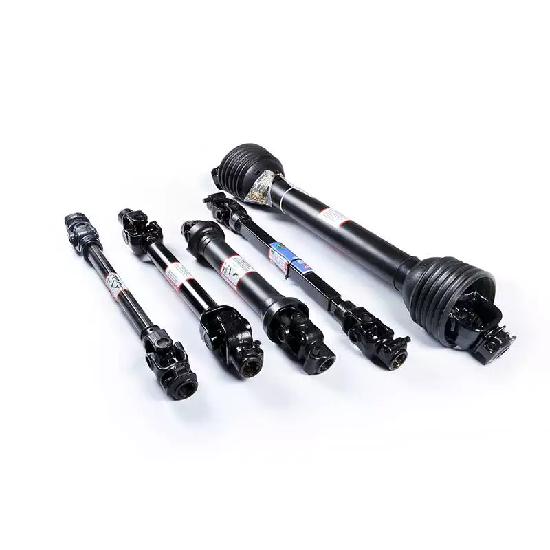
1. Telescoping Design:
– PTO drivelines often feature a telescoping design, allowing for adjustable length. Telescoping drivelines consist of two or more shaft sections that can slide within one another, similar to a telescope. This design enables the driveline to extend or retract to match the required length for connecting the power source (e.g., tractor) to the implement. By adjusting the length, telescoping drivelines can accommodate variations in the distance between the power source and the implement, ensuring a proper fit and efficient power transfer.
2. Splined Connections:
– PTO drivelines commonly use splined connections to ensure secure and reliable power transmission. Splines are ridges or grooves on the driveline shaft and corresponding mating components. They provide a positive engagement and torque transfer between the driving and driven shafts. Splined connections allow for variations in length and also provide some flexibility in alignment. By sliding the shaft sections within the telescoping design, operators can align the splined connections to achieve proper engagement and compensate for small misalignments.
3. Shear Pins and Slip Clutches:
– PTO drivelines incorporate shear pins or slip clutches as safety devices to protect against sudden overloads or obstructions. Shear pins are designed to break when excessive torque is applied to the driveline, preventing damage to the driveline components. Slip clutches, on the other hand, allow for controlled slippage when a certain torque threshold is exceeded. These safety mechanisms not only protect the driveline but also accommodate slight variations in length and sudden changes in load. They provide a degree of flexibility and help prevent driveline damage in case of unexpected stress or resistance.
4. Interchangeable Components:
– PTO drivelines often utilize interchangeable components, such as yokes, couplings, and adapters, to accommodate different connection methods. These components allow for compatibility between the driveline and various implements or equipment. For example, driveline yokes are available in different sizes, styles, and connection types, such as round, square, or hexagonal bores. This interchangeability enables operators to select the appropriate components that match the connection methods used by their specific equipment, ensuring a secure and proper fit.
5. Manufacturer Specifications:
– PTO drivelines are designed and manufactured according to specific standards and guidelines provided by the manufacturers. These specifications outline the maximum and minimum length requirements, connection methods, torque ratings, and other parameters necessary for safe and efficient operation. Operators should refer to the manufacturer’s guidelines and recommendations to ensure that the driveline accommodates any variations in length and connection methods within the specified limits.
6. Customization and Adaptation:
– In some cases, PTO drivelines may require customization or adaptation to accommodate unique length or connection requirements. This can involve modifying the length of the driveline shafts, using different adapters or couplings, or even ordering custom-made driveline assemblies. Consulting with driveline manufacturers, equipment suppliers, or driveline specialists can help determine the best approach for accommodating specific variations in length and connection methods.
In summary, PTO drivelines accommodate variations in length and connection methods through telescoping designs, splined connections, shear pins, slip clutches, interchangeable components, and adherence to manufacturer specifications. These features ensure flexibility, compatibility, and reliable power transfer between the power source and the implement, regardless of the specific length or connection requirements of the equipment or application.

How do PTO drivelines handle fluctuations in load and torque during operation?
PTO (Power Take-Off) drivelines are designed to handle fluctuations in load and torque during operation to ensure efficient power transfer and protect the driveline components. Here are the key aspects of how PTO drivelines handle these fluctuations:
1. Torque Limiting Devices:
– PTO drivelines often incorporate torque limiting devices to protect against excessive torque and sudden fluctuations in load. These devices, such as shear pins, slip clutches, or overload clutches, are designed to disconnect or slip when the torque exceeds a predetermined limit. By disengaging or slipping, these devices prevent damage to the driveline components and the connected machinery. Once the torque returns to a safe level, the driveline can resume normal operation.
2. Torque Converters:
– Some PTO drivelines utilize torque converters to handle fluctuations in load and torque. Torque converters are fluid coupling devices that provide a smooth and gradual transfer of torque. They can absorb and dampen sudden changes in load, providing a buffer between the power source and the driven equipment. Torque converters can help minimize stress on the driveline components and reduce the impact of load fluctuations on the overall system.
3. Spring-Loaded Tensioners:
– PTO drivelines often incorporate spring-loaded tensioners to maintain proper tension in the driveline. These tensioners ensure that the driveline remains engaged and properly aligned during operation, even when there are fluctuations in load or torque. The spring-loaded mechanism allows the tensioner to automatically adjust and compensate for changes in tension, helping to minimize slack and ensure consistent power transmission.
4. Robust Driveline Components:
– PTO driveline components, such as shafts, universal joints, and yokes, are designed to be robust and capable of handling fluctuations in load and torque. They are typically manufactured using high-strength materials and undergo rigorous testing to ensure durability and performance. The driveline components are engineered to withstand the anticipated loads and torque variations encountered during operation, reducing the risk of failures or premature wear.
5. Proper Lubrication:
– Adequate lubrication of the driveline components is essential for handling load and torque fluctuations. Proper lubrication helps reduce friction, dissipate heat, and maintain smooth operation even under varying loads. Lubrication also contributes to the longevity and reliability of the driveline components by minimizing wear and preventing damage due to excessive friction. Regular lubrication maintenance according to the manufacturer’s recommendations is crucial for optimal performance.
6. Operator Skill and Awareness:
– The operator’s skill and awareness play a significant role in handling load and torque fluctuations in PTO drivelines. Operators should be trained to operate the equipment within safe load limits and to anticipate and respond to changes in load or torque. Proper monitoring of the equipment during operation can help identify any abnormal fluctuations and take appropriate action to prevent damage to the driveline components.
7. System Design and Engineering:
– PTO drivelines are designed and engineered with load and torque fluctuations in mind. System designers analyze the expected operating conditions and select appropriate driveline components and configurations to ensure reliable performance. Factors such as the anticipated load variations, duty cycles, and equipment requirements are considered during the design phase to create a driveline system that can handle the expected fluctuations in load and torque.
In summary, PTO drivelines handle fluctuations in load and torque through the use of torque limiting devices, torque converters, spring-loaded tensioners, robust driveline components, proper lubrication, operator skill and awareness, and thoughtful system design. These features and considerations contribute to the safe and efficient operation of PTO drivelines, allowing them to adapt to changing load conditions while protecting the driveline components and the connected machinery.

How do PTO drivelines contribute to power transmission from tractors to implements?
PTO (Power Take-Off) drivelines play a crucial role in facilitating power transmission from tractors to implements in agricultural and industrial applications. They provide a reliable and efficient mechanism for transferring rotational power from the tractor’s engine to various implements. Let’s explore how PTO drivelines contribute to power transmission in more detail:
1. Direct Power Transfer:
A PTO driveline allows for direct power transfer from the tractor’s engine to the implement. When the PTO is engaged, the rotational power generated by the engine is transmitted through the driveline without the need for additional power sources or intermediate components. This direct power transfer ensures efficiency and minimizes power losses, allowing the implement to receive the full power output of the tractor’s engine.
2. Rotational Speed and Torque:
PTO drivelines enable the adjustment of rotational speed and torque to match the requirements of different implements. Tractors often have multiple PTO speed options, typically 540 or 1,000 revolutions per minute (RPM), although other speeds may be available. The PTO driveline allows the operator to select the appropriate speed for the implement being used. This flexibility ensures that the implement operates at the optimal speed, maximizing its efficiency and performance.
3. Standardization and Compatibility:
PTO drivelines are standardized across different tractor makes and models, ensuring compatibility with a wide range of implements. There are industry-standard PTO shaft sizes and configurations, such as the 6-spline or 21-spline shafts, which allow for easy connection between the tractor and implement. This standardization and compatibility enable farmers and operators to use a variety of implements with their tractors, expanding the versatility and functionality of their equipment.
4. Safety Features:
PTO drivelines incorporate safety features to protect operators and prevent accidents. One important safety feature is the PTO clutch, which allows for the engagement and disengagement of the power transmission. The clutch provides control over the power transfer process, allowing operators to stop the power flow when necessary, such as during implement attachment or detachment. Safety shields or guards are also commonly used to cover the rotating PTO shaft, preventing accidental contact and reducing the risk of injury.
5. Ease of Use:
PTO drivelines are designed for ease of use, making it convenient for operators to connect and disconnect implements. Implement attachment typically involves aligning the PTO shaft with the implement’s input shaft and securing it with a locking mechanism or a quick coupler. This process is relatively straightforward and can be done quickly, allowing for efficient implement changes during operations. The ease of use provided by PTO drivelines saves time and enhances productivity in agricultural and industrial settings.
6. Versatility and Productivity:
PTO drivelines contribute to the versatility and productivity of agricultural and industrial machinery. The ability to connect a wide range of implements, such as mowers, balers, seeders, and sprayers, to the tractor through the PTO driveline enables operators to perform various tasks with a single machine. This versatility eliminates the need for multiple dedicated power sources or specialized equipment, optimizing resource utilization and maximizing productivity in farming and industrial operations.
Overall, PTO drivelines play a vital role in enabling power transmission from tractors to implements. Through direct power transfer, adjustable rotational speed and torque, standardization and compatibility, safety features, ease of use, and versatility, PTO drivelines ensure efficient and effective power transmission. They enhance the functionality and productivity of agricultural and industrial machinery, enabling operators to accomplish a wide range of tasks with their tractors and implements.
editor by CX 2023-09-21
China Custom Well Reputation Dq754 75HP 4WD Four Wheel Agricultural Farming Tractor for Sale pto shaft bush hog
Product Description
Well Reputation Dq754 75HP 4WD Four Wheel Agricultural Farming Tractor for Sale
Tractor Main Features and Advantages:
1.Equipped famous brand engine showing advanced capacity,low fuel consumption,high economic efficiency.
2. Streamlined appearance design, beautiful and generous.
3.Transmission Case adopt meshed shift and add the gearbox interlock device makes the operation more smoothly,reliable and easier.
4. Double action clutch with disc spring, perform steadily and easy to operate.
5. Fully hydraulic steering system greatly reduced driver’s work strength.
6. Wet disc brake device, reliable brake performance.
7. Separate injection of hydraulic oil, reliable to operate.
8. The lifter with force and position adjustment, with reliable lift.
9. Tractor PTO:
PTO in Double speed : 540/760r/min Optional, For high working efficiency.
PTO shaft of 6 or 8 spline Optional, adaptable for agricultural equipment of all over the world.
10. Big Chassis and Heavy-duty Rear axle for Durable Strong machine.
11. Full series light, ROPS,Sunshade/Canopy, Fan/Heater/Air-conditioned cabin are all available, for more comfortable driving environment.
Tractor Main specificaiton and Technical parameters:
| Model | DQ754B | ||||||||||||||||||||||||||||||||||||||||||||||||||||||||||||||||||||||||||||||||||||||||||||||||||||||||||||||||||||||||||||||||||||||||||||||||||||||||||||||||||||||||||||||||||||||||||||||||||||||||||||||||||||||||||||||||||||||||||||||||||||||||||||||||||||||||||||||||||||||||||||||||||||||||||||||||||||||||||||||||||||||||||||||||||||||||||||||||||||||||||||||||||||||||
| Drive type | 4×4 | ||||||||||||||||||||||||||||||||||||||||||||||||||||||||||||||||||||||||||||||||||||||||||||||||||||||||||||||||||||||||||||||||||||||||||||||||||||||||||||||||||||||||||||||||||||||||||||||||||||||||||||||||||||||||||||||||||||||||||||||||||||||||||||||||||||||||||||||||||||||||||||||||||||||||||||||||||||||||||||||||||||||||||||||||||||||||||||||||||||||||||||||||||||||||
| Engine | |||||||||||||||||||||||||||||||||||||||||||||||||||||||||||||||||||||||||||||||||||||||||||||||||||||||||||||||||||||||||||||||||||||||||||||||||||||||||||||||||||||||||||||||||||||||||||||||||||||||||||||||||||||||||||||||||||||||||||||||||||||||||||||||||||||||||||||||||||||||||||||||||||||||||||||||||||||||||||||||||||||||||||||||||||||||||||||||||||||||||||||||||||||||||
| Engine model | YTO, 4-Cylinder diesel engine | ||||||||||||||||||||||||||||||||||||||||||||||||||||||||||||||||||||||||||||||||||||||||||||||||||||||||||||||||||||||||||||||||||||||||||||||||||||||||||||||||||||||||||||||||||||||||||||||||||||||||||||||||||||||||||||||||||||||||||||||||||||||||||||||||||||||||||||||||||||||||||||||||||||||||||||||||||||||||||||||||||||||||||||||||||||||||||||||||||||||||||||||||||||||||
| Capacity of fuel tank (L) | 78 | ||||||||||||||||||||||||||||||||||||||||||||||||||||||||||||||||||||||||||||||||||||||||||||||||||||||||||||||||||||||||||||||||||||||||||||||||||||||||||||||||||||||||||||||||||||||||||||||||||||||||||||||||||||||||||||||||||||||||||||||||||||||||||||||||||||||||||||||||||||||||||||||||||||||||||||||||||||||||||||||||||||||||||||||||||||||||||||||||||||||||||||||||||||||||
| Engine power at rated speed (kw/hp) | 55.2kw/75HP | ||||||||||||||||||||||||||||||||||||||||||||||||||||||||||||||||||||||||||||||||||||||||||||||||||||||||||||||||||||||||||||||||||||||||||||||||||||||||||||||||||||||||||||||||||||||||||||||||||||||||||||||||||||||||||||||||||||||||||||||||||||||||||||||||||||||||||||||||||||||||||||||||||||||||||||||||||||||||||||||||||||||||||||||||||||||||||||||||||||||||||||||||||||||||
| PTO power at rated speed (kw) | 46.8 | ||||||||||||||||||||||||||||||||||||||||||||||||||||||||||||||||||||||||||||||||||||||||||||||||||||||||||||||||||||||||||||||||||||||||||||||||||||||||||||||||||||||||||||||||||||||||||||||||||||||||||||||||||||||||||||||||||||||||||||||||||||||||||||||||||||||||||||||||||||||||||||||||||||||||||||||||||||||||||||||||||||||||||||||||||||||||||||||||||||||||||||||||||||||||
| Transmission | |||||||||||||||||||||||||||||||||||||||||||||||||||||||||||||||||||||||||||||||||||||||||||||||||||||||||||||||||||||||||||||||||||||||||||||||||||||||||||||||||||||||||||||||||||||||||||||||||||||||||||||||||||||||||||||||||||||||||||||||||||||||||||||||||||||||||||||||||||||||||||||||||||||||||||||||||||||||||||||||||||||||||||||||||||||||||||||||||||||||||||||||||||||||||
| Steering type | Full Hydraulic Steering | ||||||||||||||||||||||||||||||||||||||||||||||||||||||||||||||||||||||||||||||||||||||||||||||||||||||||||||||||||||||||||||||||||||||||||||||||||||||||||||||||||||||||||||||||||||||||||||||||||||||||||||||||||||||||||||||||||||||||||||||||||||||||||||||||||||||||||||||||||||||||||||||||||||||||||||||||||||||||||||||||||||||||||||||||||||||||||||||||||||||||||||||||||||||||
| Clutch | Dry,Dual-stage type | ||||||||||||||||||||||||||||||||||||||||||||||||||||||||||||||||||||||||||||||||||||||||||||||||||||||||||||||||||||||||||||||||||||||||||||||||||||||||||||||||||||||||||||||||||||||||||||||||||||||||||||||||||||||||||||||||||||||||||||||||||||||||||||||||||||||||||||||||||||||||||||||||||||||||||||||||||||||||||||||||||||||||||||||||||||||||||||||||||||||||||||||||||||||||
| PTO Speed (rpm) | 540/760 | ||||||||||||||||||||||||||||||||||||||||||||||||||||||||||||||||||||||||||||||||||||||||||||||||||||||||||||||||||||||||||||||||||||||||||||||||||||||||||||||||||||||||||||||||||||||||||||||||||||||||||||||||||||||||||||||||||||||||||||||||||||||||||||||||||||||||||||||||||||||||||||||||||||||||||||||||||||||||||||||||||||||||||||||||||||||||||||||||||||||||||||||||||||||||
| Gearshift | 8F Best price will be quoted for you as soon as receive your Requirement !
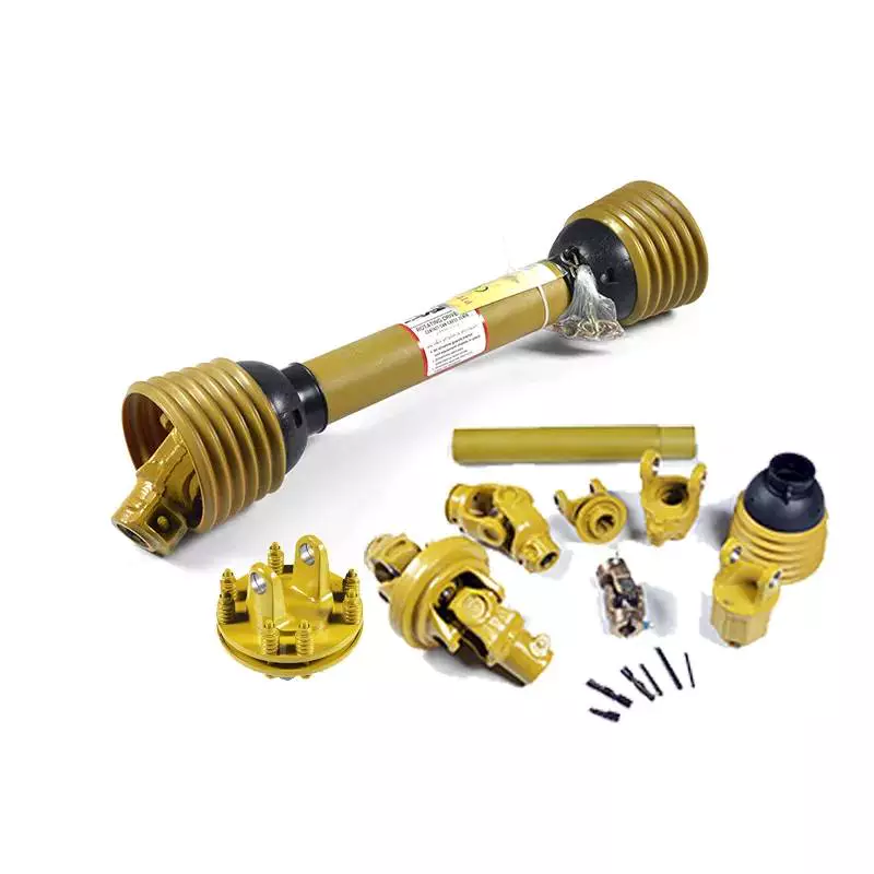
The Different Parts of a PTO ShaftPower Take-Off (PTO) shafts are an integral part of a tractor’s driveline. Without them, a tractor cannot operate. It is essential to understand the different parts of a PTO shaft, as they are crucial for the operation of your tractor. These parts are typically overlooked during routine tractor maintenance checks, but knowing more about them will help you practice on farm machinery better. Tractor’s power take-off (PTO) shaftA Tractor’s power take-off (or PTO) shaft transfers power from the tractor to an implement. These shafts typically rotate at speeds between 540 and 1000 rpm. A number of safety features help prevent accidental contact between the shaft and the implement. TypesPTO shafts come in a variety of different shapes, sizes, and materials. The most common types are square and round, but there are also star-shaped and trilobed types. While the star-shaped type is a typical North American design, the trilobed and lemon-shaped varieties are typically German or Italian. Typically, the lemon-shaped ones are made of an alloy called ‘Lemon Yellow.’ In some cases, the shaft will come with snap rings. Rotation directionThe PTO shaft is a critical part of the power take-off of a farm tractor. It allows the tractor to transfer power from the engine to an implement such as a mower or other garden equipment. The rotation direction of the PTO shaft depends on the type of implement. Some implements only accept rotation in one direction, while others require rotation in both directions. Safety chain
Shield
China Professional High Quality Ce Oecd Approved Dq804b 80HP 4WD Agricultural Wheel Farming Tractor with Rops for Sale pto shaft came apartProduct Description
High quality CE OECD approved DQ804B 80HP 4WD Agricultural wheel Farming tractor with ROPS for sale Tractor Main Features and Advantages: Tractor Main specificaiton and Technical parameters:
Advance Manufacutring Line: Strictly Inspecting and Full Testing for ensuring high quality product: High quality DQ804B 80HP 4WD tractor have different Optional configurations for choose:
Best price will be quoted for you as soon as receive your Requirement !
Choosing the Right PTO for Your MachineThere are many types of PTOs, and you may be wondering which one is the best choice for your machine. In this article, you’ll learn about Splined PTOs, Reverse PTOs, and Independent PTOs. Choosing the right PTO for your needs will allow you to operate your machine more efficiently. LPTOLPTOs can be dangerous for operators. They should stay at a safe distance from them to avoid getting entangled in the rotating shaft. If an operator gets caught, he or she could sustain severe injuries or even death. Safety precautions include wearing clothing that does not cling to the shaft. Reverse PTOThere are several different ways to reverse the PTO shaft. Some older Massey Ferguson style tractors are designed to reverse the PTO shaft by turning it backward. This feature is useful for raising upright silo unloaders. The first method involves driving backward with the rear wheel jacked up and rotating while the rear wheel spins. This method is also useful for reversing a baler or unplugging a baler. Splined PTOThe splined PTO shaft consists of six equal-sized splines that are spaced apart by grooves. The splines are angled to the axis of rotation of the PTO shaft. When the splines and the grooves meet, they align the screw end portion. Independent PTOIndependent PTO shafts can be mechanical or hydraulic. The mechanical type has a separate on/off selector and control lever, whereas hydraulic PTOs have just one. The mechanical version is preferred for tractors that need to operate at lower speeds and for applications such as baling and tilling. The hydraulic version reduces noise and vibration. LPTO shaft guardAn LPTO shaft guard prevents accidental rotational collisions by covering the shaft of a PTO. A PTO shaft is a moving part that can entrap a person’s legs, arms, and clothing. In a pinch, a person could become entangled in the shaft and suffer a serious injury. A PTO shaft guard is a great way to protect yourself against these dangerous incidents. Safety of handling a pto shaftHandling a PTO shaft safely is a vital component of tractor safety. Safety shields must be properly fastened to the shaft to prevent any accidents. The shield should also be inspected and maintained regularly. Otherwise, foreign materials, including clothing, can enter the shaft’s bearings. It is also important to walk around the rotating shaft whenever possible. China high quality agriculture machinery mini farm tractor mounted green machine road snow sweepers for sale agricultural parts directEquipment Kind: Flooring Sweeper Items Description actor highway sweeper: 1. SX Collection Snow Sweeper for tractor is used for sweeping of thin layer of snow, showcased with fast velocity, higher effectiveness andeasy procedure. To distinct away deep snow, it will be far more successful to use it with each other with snow blade. It is also used in sweepingon street and floor.2. SX Series Snow Sweeper for tractor is commonly employed in highway, Custom Substantial Quality Agriculture Equipment Tractor Elements Driveline Cardan Drive PTO Shaft ground, warehouse and so forth, mostly in sweeping of skinny layer of snow,leaves, sand, courtroom and so forth.3.The snow sweeper can be matched to tractor,wheel loader, Stober K514SG3000EK501U Gear Head Velocity Reducers forklift,4.The snow sweeper driven by hydraulic output of these equipment,only tractor could be pushed by PTO.5.PP with metal wires brushes.6.Working width from 1200 to 2500mm7.Suited for cleansing highway,avenue,floor and other flat. Product Technical specs
Calculating the Deflection of a Worm ShaftIn this article, we’ll discuss how to calculate the deflection of a worm gear’s worm shaft. We’ll also discuss the characteristics of a worm gear, including its tooth forces. And we’ll cover the important characteristics of a worm gear. Read on to learn more! Here are some things to consider before purchasing a worm gear. We hope you enjoy learning! After reading this article, you’ll be well-equipped to choose a worm gear to match your needs. Calculation of worm shaft deflectionThe main goal of the calculations is to determine the deflection of a worm. Worms are used to turn gears and mechanical devices. This type of transmission uses a worm. The worm diameter and the number of teeth are inputted into the calculation gradually. Then, a table with proper solutions is shown on the screen. After completing the table, you can then move on to the main calculation. You can change the strength parameters as well. Influence of tooth forces on bending stiffness of a worm gearThe bending stiffness of a worm gear is dependent on tooth forces. Tooth forces increase as the power density increases, but this also leads to increased worm shaft deflection. The resulting deflection can affect efficiency, wear load capacity, and NVH behavior. Continuous improvements in bronze materials, lubricants, and manufacturing quality have enabled worm gear manufacturers to produce increasingly high power densities. Characteristics of worm gearsWorm gears are unique types of gears. They feature a variety of characteristics and applications. This article will examine the characteristics and benefits of worm gears. Then, we’ll examine the common applications of worm gears. Let’s take a look! Before we dive in to worm gears, let’s review their capabilities. Hopefully, you’ll see how versatile these gears are.
China manufacturer China Manufacturer Tractor 4X4 Wheel 4WD Agricultural Machinery 40HP 50HP 60HP 70HP 80HP 90HP 100HP 120HP 160HP 220HP Farm Tractor for Sale near me factoryProduct Description
Product Description
Features:
How to Choose the Right Worm ShaftYou might be curious to know how to choose the right Worm Shaft. In this article, you will learn about worm modules with the same pitch diameter, Double-thread worm gears, and Self-locking worm drive. Once you have chosen the proper Worm Shaft, you will find it easier to use the equipment in your home. There are many advantages to selecting the right Worm Shaft. Read on to learn more. Concave shapeThe concave shape of a worm’s shaft is an important characteristic for the design of a worm gearing. Worm gearings can be found in a wide range of shapes, and the basic profile parameters are available in professional and firm literature. These parameters are used in geometry calculations, and a selection of the right worm gearing for a particular application can be based on these requirements. Multiple-thread wormsMulti-thread worms can be divided into sets of one, two, or four threads. The ratio is determined by the number of threads on each set and the number of teeth on the apparatus. The most common worm thread counts are 1,2,4, and 6. To find out how many threads you have, count the start and end of each thread and divide by two. Using this method, you will get the correct thread count every time. Double-thread worm gearsIn many different applications, worm gears are used to drive a worm wheel. These gears are unique in that the worm cannot be reversed by the power applied to the worm wheel. Because of their self-locking properties, they can be used to prevent reversing motion, although this is not a dependable function. Applications for worm gears include hoisting equipment, elevators, chain blocks, fishing reels, and automotive power steering. Because of their compact size, these gears are often used in applications with limited space. Self-locking worm driveA self-locking worm drive prevents the platform from moving backward when the motor stops. A dynamic self-locking worm drive is also possible but does not include a holding brake. This type of self-locking worm drive is not susceptible to vibrations, but may rattle if released. In addition, it may require an additional brake to keep the platform from moving. A positive brake may be necessary for safety.
| ||||||||||||||||||||||||||||||||||||||||||||||||||||||||||||||||||||||||||||||||||||||||||||||||||||||||||||||||||||||||||||||||||||||||||||||||||||||||||||||||||||||||||||||||||||||||||||||||||||||||||||||||||||||||||||||||||||||||||||||||||||||||||||||||||||||||||||||||||||||||||||||||||||||||||||||||||||||||||||||||||||||||||||||||||||||||||||||||||||||||||||||||||||||||
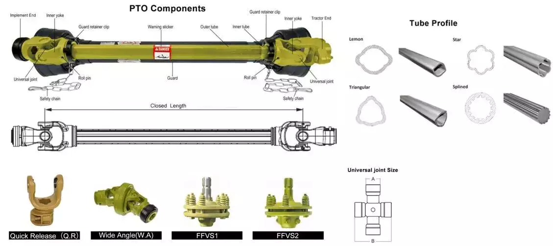 One of the best ways to protect your PTO shaft is to use a safety chain. A safety chain is a chain that is attached to the PTO shaft, and it prevents the plastic shield from spinning on the shaft. This chain should be fastened to a suitable point on your machine or tractor. It should not be attached to the lower lift arms or the U-guard.
 A PTO shaft shield protects the PTO shaft from possible impacts. It is typically made of plastic, but can also be made of metal. These shields are easy to damage, and are therefore preferably made of a durable material. The shields are held in place with brackets. The shields are made with two parts: an inner shield and a protective sleeve.