Product Description
| Size | 260 cm * 120 cm * 135 cm |
| Drive Wheel | 4WD |
| Power | 12(Kw) |
| Specification | 30-50HP |
| Fuel | Gas / Diesel |
| Weight | 680(kg) |
| Tyres sizes | 500-12/650-16 |
| Usage | Farm Tractor, Garden Tractor, Lawn Tractor |
This is part of the certificate, please contact us if you need more!
We can provide customers with customizable packaging, a large number of goods in stock, and a wide choice of freight routes.
Q1: Can I have a sample order?
A1: Yes, we accept sample order to test and check quality.
Q2: Do you have MOQ limit?
A2: Yes, we have MOQ limit for mass production, but it depends on model. Please contact us for details.
Q3: How about the lead time?
A3: Samples will takes 5-7 business days. Mass production will takes 25-30 days. It depends on quantity.
Q4: How about shipping and delivery time?
A4: Generally, Item will be shipped via Express, such as DHL, TNT, FedEx and UPS, delivery time is 3-7 business days. Airline and sea shipping also available.
In order to better serve customers, we now make the following disclaimer for the product information published on the website that contains text, pictures, and links:
1. The product picture may have a color difference with the actual product due to the different angle and light, as well as the display difference of the monitor. The picture is for reference only, the actual product shall prevail, please contact our staff for more details.
2. It is the customized product, not final retail product. Details, description, pictures, and specifications are subject to the final confirmed order.
3. The price is for reference only, the market price is fluctuating, and the price marked on this page is not the only basis for the final transaction. Please contact our sales staff to confirm the final price.
/* January 22, 2571 19:08:37 */!function(){function s(e,r){var a,o={};try{e&&e.split(“,”).forEach(function(e,t){e&&(a=e.match(/(.*?):(.*)$/))&&1
| After-sales Service: | 6 Months |
|---|---|
| Warranty: | 6 Months |
| Type: | Wheel Tractor |
| Samples: |
US$ 16999/Piece
1 Piece(Min.Order) | Order Sample |
|---|
| Customization: |
Available
| Customized Request |
|---|
.shipping-cost-tm .tm-status-off{background: none;padding:0;color: #1470cc}
|
Shipping Cost:
Estimated freight per unit. |
about shipping cost and estimated delivery time. |
|---|
| Payment Method: |
|
|---|---|
|
Initial Payment Full Payment |
| Currency: | US$ |
|---|
| Return&refunds: | You can apply for a refund up to 30 days after receipt of the products. |
|---|

What factors should be considered when selecting the appropriate PTO driveline for an application?
When selecting the appropriate PTO (Power Take-Off) driveline for an application, several factors need to be considered to ensure optimal performance, efficiency, and safety. Here are some key factors to take into account:
1. Power Requirements:
– Determine the power requirements of the driven equipment. Consider the horsepower (HP) or kilowatt (kW) rating necessary to operate the equipment effectively. The PTO driveline should be capable of transmitting the required power without overloading or damaging the driveline components.
2. Speed and RPM:
– Identify the desired operating speed and RPM (Rotations Per Minute) of the driven equipment. The PTO driveline should be compatible with the required speed range to ensure efficient power transmission. Consider the maximum and minimum RPM ratings of the driveline and select one that matches the specific speed requirements of the application.
3. Torque Requirements:
– Determine the torque requirements of the driven equipment. Torque is the rotational force required to perform the intended task. Consider both the maximum and average torque demands during operation. Ensure that the selected PTO driveline can handle the torque levels without exceeding its maximum torque capacity or causing premature wear or failure.
4. Application Type:
– Consider the specific application and the type of equipment involved. Different applications may require different PTO driveline designs and features. For example, agricultural equipment such as mowers, balers, or tillers may benefit from a constant velocity (CV) PTO driveline to accommodate varying angles and speeds, while stationary equipment like generators or water pumps may use a non-constant velocity (non-CV) PTO driveline.
5. Safety Considerations:
– Evaluate the safety requirements of the application. Certain applications may require additional safety features such as shear bolts or slip clutches to protect against excessive loads, sudden obstructions, or torque spikes. Ensure that the selected PTO driveline incorporates the necessary safety mechanisms to prevent damage to the driveline and equipment, as well as to ensure the safety of operators and bystanders.
6. Durability and Maintenance:
– Consider the durability and maintenance requirements of the PTO driveline. Evaluate the quality and reliability of the driveline components, such as bearings, joints, and couplings. Choose a driveline that is built to withstand the demands of the application and requires minimal maintenance to ensure long-term performance and reduce downtime.
7. Compatibility:
– Ensure compatibility between the PTO driveline and the power source (e.g., tractor, engine). Consider the PTO driveline’s connection type, size (e.g., spline count, shaft diameter), and mounting configuration to ensure a proper fit and connection with the power source.
8. Environmental Conditions:
– Take into account the environmental conditions in which the PTO driveline will operate. Factors such as temperature extremes, exposure to moisture, dust, or chemicals can impact the driveline’s performance and longevity. Choose a driveline that is designed to withstand the specific environmental conditions of the application.
9. Manufacturer and Quality:
– Consider the reputation and reliability of the PTO driveline manufacturer. Opt for reputable manufacturers known for producing high-quality and durable driveline systems. Research customer reviews and seek recommendations from industry experts to ensure you choose a reliable and reputable brand.
By carefully considering these factors, you can select the most appropriate PTO driveline for your specific application. It is recommended to consult with manufacturers, industry experts, or equipment dealers to get further guidance and ensure the right driveline selection for your needs.

How do PTO drivelines enhance the performance of tractors and agricultural equipment?
PTO (Power Take-Off) drivelines play a crucial role in enhancing the performance of tractors and agricultural equipment. By providing a reliable and versatile power source, PTO drivelines improve the functionality, efficiency, and productivity of agricultural machinery. Here are several ways in which PTO drivelines enhance the performance of tractors and agricultural equipment:
1. Power Versatility:
– PTO drivelines enable tractors and agricultural equipment to utilize a wide range of power-driven implements and attachments. By connecting to the PTO shaft of a tractor, implements such as mowers, tillers, seeders, and balers can be powered directly, eliminating the need for separate engines or motors. This versatility allows farmers to perform multiple tasks using a single power source, reducing equipment redundancy and increasing operational efficiency.
2. Increased Efficiency:
– PTO drivelines contribute to increased efficiency by providing a direct power transfer mechanism. The driveline ensures minimal power loss during transmission, resulting in more efficient utilization of available power. This efficiency leads to improved performance and reduced fuel consumption, ultimately optimizing resource utilization and lowering operating costs.
3. Flexibility in Equipment Usage:
– PTO drivelines offer flexibility in equipment usage by allowing quick and easy attachment and detachment of implements. Farmers can rapidly switch between different implements, tailoring the equipment to suit specific tasks and field conditions. This flexibility enhances productivity as it reduces downtime associated with changing equipment, enabling farmers to adapt to changing agricultural needs efficiently.
4. Time Savings:
– PTO drivelines contribute to time savings by enabling faster and more efficient completion of agricultural tasks. Machinery powered by PTO drivelines can operate at higher speeds and cover larger areas, reducing the time required for tasks such as mowing, tilling, planting, and harvesting. Additionally, the direct power transfer provided by PTO drivelines eliminates the need for manual labor or slower power transmission methods, further enhancing productivity and time efficiency.
5. Enhanced Capability:
– PTO drivelines enhance the capability of tractors and agricultural equipment by enabling them to handle a broader range of tasks and operate specialized implements. For example, PTO-driven sprayers allow precise and efficient spraying of fertilizers and pesticides, ensuring optimal crop health. PTO-driven balers enable efficient baling and packaging of hay or other forage materials. The versatility and enhanced capability provided by PTO drivelines allow farmers to expand their operations and achieve higher levels of productivity.
6. Consistent Power Delivery:
– PTO drivelines ensure consistent power delivery to agricultural equipment, resulting in consistent and uniform operation. The power from the tractor or power source is transmitted directly to the driven machinery, maintaining a steady power input. Consistent power delivery helps ensure optimum performance, reducing variations in output quality and minimizing the need for rework or adjustments.
7. Improved Safety:
– PTO drivelines contribute to improved safety by reducing the need for direct operator interaction with moving parts. Implements and machinery powered by PTO drivelines often have guards and safety features in place to protect operators from potential hazards. Additionally, the direct power transfer eliminates the need for manual belt or chain drives, reducing the risk of entanglement or mechanical failures.
8. Advanced Technology Integration:
– PTO drivelines enable the integration of advanced technologies and features into agricultural equipment. For example, PTO-driven machinery can incorporate precision farming technologies, such as GPS guidance systems, automatic controls, and variable-rate application capabilities. These technologies enhance accuracy, efficiency, and input optimization, resulting in improved performance and increased yields.
Overall, PTO drivelines significantly enhance the performance of tractors and agricultural equipment by providing a versatile power source, increasing efficiency, enabling flexibility in equipment usage, saving time, enhancing capability, ensuring consistent power delivery, improving safety, and facilitating the integration of advanced technologies. These advantages contribute to increased productivity, improved operational effectiveness, and enhanced profitability in agricultural operations.

What are the key components of a PTO driveline system and how do they work together?
A PTO (Power Take-Off) driveline system consists of several key components that work together to facilitate power transmission from a power source to driven equipment. Each component plays a specific role in ensuring the efficient and reliable transfer of rotational power. Let’s explore the key components of a PTO driveline system and how they work together:
1. Power Source:
The power source in a PTO driveline system is typically an engine or motor, such as the one found in a tractor or industrial machine. The power source generates rotational power, which serves as the energy source for the entire system. The power generated by the engine is harnessed and transferred to the PTO driveline for further transmission.
2. PTO Shaft:
The PTO shaft is a rotating shaft that extends from the power source to the driven equipment. It is the primary component responsible for transmitting power from the power source to the implement. The PTO shaft is connected to the power source at one end, typically through a PTO coupling, and to the driven equipment at the other end. As the power source rotates, the rotational motion is transferred along the PTO shaft to drive the implement.
3. PTO Clutch:
The PTO clutch is a mechanism that allows the operator to engage or disengage the power transfer between the power source and the driven equipment. It is usually controlled by a lever or switch within easy reach of the operator. When the PTO clutch is engaged, the power from the power source is transmitted through the PTO shaft to the implement. Conversely, disengaging the PTO clutch interrupts the power transfer, ensuring that power is only transmitted when needed. The PTO clutch provides control and safety during operation, allowing the operator to start or stop power transmission as required.
4. PTO Gearbox:
Some machinery may incorporate a PTO gearbox between the power source and the PTO shaft. The PTO gearbox is responsible for adjusting the rotational speed and torque of the power transfer. It contains a set of gears that can be switched or adjusted to modify the speed and torque output of the PTO shaft. By changing the gear ratios, the PTO gearbox allows operators to adapt the power transmission to suit different implements or tasks. This enables the use of implements that require varying rotational speeds or different levels of torque, enhancing the versatility of the PTO driveline system.
5. PTO Driven Equipment:
The driven equipment refers to the implements or machinery that receive power from the PTO driveline system. This can include a wide range of equipment, such as mowers, balers, sprayers, augers, pumps, or generators. The PTO driveline system transfers rotational power from the power source through the PTO shaft to the driven equipment, enabling them to perform their specific functions. The driven equipment may have input shafts or connections designed to receive the PTO shaft and convert the rotational power into the desired output, such as cutting, baling, spraying, or generating electricity.
These key components of a PTO driveline system work together in a coordinated manner to achieve effective power transmission. The power generated by the engine is transferred through the PTO clutch to the PTO shaft. If a PTO gearbox is present, it can adjust the speed and torque of the power before it reaches the driven equipment. The PTO shaft then transmits the rotational power to the driven equipment, allowing them to perform their intended functions. The operator has control over the power transmission process through the PTO clutch, enabling them to start or stop the power transfer as needed.
Overall, the key components of a PTO driveline system collaborate to provide a reliable and efficient means of power transmission from the power source to the driven equipment. This facilitates a wide range of agricultural and industrial applications, enhancing the functionality, versatility, and productivity of machinery in these sectors.


editor by CX 2024-03-12
China OEM for Farm Mini Tractors Small Pto Shaft Agricultural Sale 4X4 in Grass Machine Crawler El Salvador Petrol Engine Garden Tractor PTO Driveline
Product Description
| Size | 260 cm * 120 cm * 135 cm |
| Drive Wheel | 4WD |
| Power | 12(Kw) |
| Specification | 30-50HP |
| Fuel | Gas / Diesel |
| Weight | 680(kg) |
| Tyres sizes | 500-12/650-16 |
| Usage | Farm Tractor, Garden Tractor, Lawn Tractor |
This is part of the certificate, please contact us if you need more!
We can provide customers with customizable packaging, a large number of goods in stock, and a wide choice of freight routes.
Q1: Can I have a sample order?
A1: Yes, we accept sample order to test and check quality.
Q2: Do you have MOQ limit?
A2: Yes, we have MOQ limit for mass production, but it depends on model. Please contact us for details.
Q3: How about the lead time?
A3: Samples will takes 5-7 business days. Mass production will takes 25-30 days. It depends on quantity.
Q4: How about shipping and delivery time?
A4: Generally, Item will be shipped via Express, such as DHL, TNT, FedEx and UPS, delivery time is 3-7 business days. Airline and sea shipping also available.
In order to better serve customers, we now make the following disclaimer for the product information published on the website that contains text, pictures, and links:
1. The product picture may have a color difference with the actual product due to the different angle and light, as well as the display difference of the monitor. The picture is for reference only, the actual product shall prevail, please contact our staff for more details.
2. It is the customized product, not final retail product. Details, description, pictures, and specifications are subject to the final confirmed order.
3. The price is for reference only, the market price is fluctuating, and the price marked on this page is not the only basis for the final transaction. Please contact our sales staff to confirm the final price.
|
Shipping Cost:
Estimated freight per unit. |
To be negotiated |
|---|
| After-sales Service: | 6 Months |
|---|---|
| Warranty: | 6 Months |
| Type: | Wheel Tractor |
| Samples: |
US$ 16999/Piece
1 Piece(Min.Order) | Order Sample |
|---|
| Customization: |
Available
| Customized Request |
|---|

How do PTO drivelines accommodate variations in length and connection methods?
PTO (Power Take-Off) drivelines are designed to accommodate variations in length and connection methods to provide flexibility and compatibility with different equipment and applications. Here’s how PTO drivelines achieve this:
1. Telescoping Design:
– PTO drivelines often feature a telescoping design, allowing for adjustable length. Telescoping drivelines consist of two or more shaft sections that can slide within one another, similar to a telescope. This design enables the driveline to extend or retract to match the required length for connecting the power source (e.g., tractor) to the implement. By adjusting the length, telescoping drivelines can accommodate variations in the distance between the power source and the implement, ensuring a proper fit and efficient power transfer.
2. Splined Connections:
– PTO drivelines commonly use splined connections to ensure secure and reliable power transmission. Splines are ridges or grooves on the driveline shaft and corresponding mating components. They provide a positive engagement and torque transfer between the driving and driven shafts. Splined connections allow for variations in length and also provide some flexibility in alignment. By sliding the shaft sections within the telescoping design, operators can align the splined connections to achieve proper engagement and compensate for small misalignments.
3. Shear Pins and Slip Clutches:
– PTO drivelines incorporate shear pins or slip clutches as safety devices to protect against sudden overloads or obstructions. Shear pins are designed to break when excessive torque is applied to the driveline, preventing damage to the driveline components. Slip clutches, on the other hand, allow for controlled slippage when a certain torque threshold is exceeded. These safety mechanisms not only protect the driveline but also accommodate slight variations in length and sudden changes in load. They provide a degree of flexibility and help prevent driveline damage in case of unexpected stress or resistance.
4. Interchangeable Components:
– PTO drivelines often utilize interchangeable components, such as yokes, couplings, and adapters, to accommodate different connection methods. These components allow for compatibility between the driveline and various implements or equipment. For example, driveline yokes are available in different sizes, styles, and connection types, such as round, square, or hexagonal bores. This interchangeability enables operators to select the appropriate components that match the connection methods used by their specific equipment, ensuring a secure and proper fit.
5. Manufacturer Specifications:
– PTO drivelines are designed and manufactured according to specific standards and guidelines provided by the manufacturers. These specifications outline the maximum and minimum length requirements, connection methods, torque ratings, and other parameters necessary for safe and efficient operation. Operators should refer to the manufacturer’s guidelines and recommendations to ensure that the driveline accommodates any variations in length and connection methods within the specified limits.
6. Customization and Adaptation:
– In some cases, PTO drivelines may require customization or adaptation to accommodate unique length or connection requirements. This can involve modifying the length of the driveline shafts, using different adapters or couplings, or even ordering custom-made driveline assemblies. Consulting with driveline manufacturers, equipment suppliers, or driveline specialists can help determine the best approach for accommodating specific variations in length and connection methods.
In summary, PTO drivelines accommodate variations in length and connection methods through telescoping designs, splined connections, shear pins, slip clutches, interchangeable components, and adherence to manufacturer specifications. These features ensure flexibility, compatibility, and reliable power transfer between the power source and the implement, regardless of the specific length or connection requirements of the equipment or application.

How do PTO drivelines handle fluctuations in load and torque during operation?
PTO (Power Take-Off) drivelines are designed to handle fluctuations in load and torque during operation to ensure efficient power transfer and protect the driveline components. Here are the key aspects of how PTO drivelines handle these fluctuations:
1. Torque Limiting Devices:
– PTO drivelines often incorporate torque limiting devices to protect against excessive torque and sudden fluctuations in load. These devices, such as shear pins, slip clutches, or overload clutches, are designed to disconnect or slip when the torque exceeds a predetermined limit. By disengaging or slipping, these devices prevent damage to the driveline components and the connected machinery. Once the torque returns to a safe level, the driveline can resume normal operation.
2. Torque Converters:
– Some PTO drivelines utilize torque converters to handle fluctuations in load and torque. Torque converters are fluid coupling devices that provide a smooth and gradual transfer of torque. They can absorb and dampen sudden changes in load, providing a buffer between the power source and the driven equipment. Torque converters can help minimize stress on the driveline components and reduce the impact of load fluctuations on the overall system.
3. Spring-Loaded Tensioners:
– PTO drivelines often incorporate spring-loaded tensioners to maintain proper tension in the driveline. These tensioners ensure that the driveline remains engaged and properly aligned during operation, even when there are fluctuations in load or torque. The spring-loaded mechanism allows the tensioner to automatically adjust and compensate for changes in tension, helping to minimize slack and ensure consistent power transmission.
4. Robust Driveline Components:
– PTO driveline components, such as shafts, universal joints, and yokes, are designed to be robust and capable of handling fluctuations in load and torque. They are typically manufactured using high-strength materials and undergo rigorous testing to ensure durability and performance. The driveline components are engineered to withstand the anticipated loads and torque variations encountered during operation, reducing the risk of failures or premature wear.
5. Proper Lubrication:
– Adequate lubrication of the driveline components is essential for handling load and torque fluctuations. Proper lubrication helps reduce friction, dissipate heat, and maintain smooth operation even under varying loads. Lubrication also contributes to the longevity and reliability of the driveline components by minimizing wear and preventing damage due to excessive friction. Regular lubrication maintenance according to the manufacturer’s recommendations is crucial for optimal performance.
6. Operator Skill and Awareness:
– The operator’s skill and awareness play a significant role in handling load and torque fluctuations in PTO drivelines. Operators should be trained to operate the equipment within safe load limits and to anticipate and respond to changes in load or torque. Proper monitoring of the equipment during operation can help identify any abnormal fluctuations and take appropriate action to prevent damage to the driveline components.
7. System Design and Engineering:
– PTO drivelines are designed and engineered with load and torque fluctuations in mind. System designers analyze the expected operating conditions and select appropriate driveline components and configurations to ensure reliable performance. Factors such as the anticipated load variations, duty cycles, and equipment requirements are considered during the design phase to create a driveline system that can handle the expected fluctuations in load and torque.
In summary, PTO drivelines handle fluctuations in load and torque through the use of torque limiting devices, torque converters, spring-loaded tensioners, robust driveline components, proper lubrication, operator skill and awareness, and thoughtful system design. These features and considerations contribute to the safe and efficient operation of PTO drivelines, allowing them to adapt to changing load conditions while protecting the driveline components and the connected machinery.

How do PTO drivelines contribute to power transmission from tractors to implements?
PTO (Power Take-Off) drivelines play a crucial role in facilitating power transmission from tractors to implements in agricultural and industrial applications. They provide a reliable and efficient mechanism for transferring rotational power from the tractor’s engine to various implements. Let’s explore how PTO drivelines contribute to power transmission in more detail:
1. Direct Power Transfer:
A PTO driveline allows for direct power transfer from the tractor’s engine to the implement. When the PTO is engaged, the rotational power generated by the engine is transmitted through the driveline without the need for additional power sources or intermediate components. This direct power transfer ensures efficiency and minimizes power losses, allowing the implement to receive the full power output of the tractor’s engine.
2. Rotational Speed and Torque:
PTO drivelines enable the adjustment of rotational speed and torque to match the requirements of different implements. Tractors often have multiple PTO speed options, typically 540 or 1,000 revolutions per minute (RPM), although other speeds may be available. The PTO driveline allows the operator to select the appropriate speed for the implement being used. This flexibility ensures that the implement operates at the optimal speed, maximizing its efficiency and performance.
3. Standardization and Compatibility:
PTO drivelines are standardized across different tractor makes and models, ensuring compatibility with a wide range of implements. There are industry-standard PTO shaft sizes and configurations, such as the 6-spline or 21-spline shafts, which allow for easy connection between the tractor and implement. This standardization and compatibility enable farmers and operators to use a variety of implements with their tractors, expanding the versatility and functionality of their equipment.
4. Safety Features:
PTO drivelines incorporate safety features to protect operators and prevent accidents. One important safety feature is the PTO clutch, which allows for the engagement and disengagement of the power transmission. The clutch provides control over the power transfer process, allowing operators to stop the power flow when necessary, such as during implement attachment or detachment. Safety shields or guards are also commonly used to cover the rotating PTO shaft, preventing accidental contact and reducing the risk of injury.
5. Ease of Use:
PTO drivelines are designed for ease of use, making it convenient for operators to connect and disconnect implements. Implement attachment typically involves aligning the PTO shaft with the implement’s input shaft and securing it with a locking mechanism or a quick coupler. This process is relatively straightforward and can be done quickly, allowing for efficient implement changes during operations. The ease of use provided by PTO drivelines saves time and enhances productivity in agricultural and industrial settings.
6. Versatility and Productivity:
PTO drivelines contribute to the versatility and productivity of agricultural and industrial machinery. The ability to connect a wide range of implements, such as mowers, balers, seeders, and sprayers, to the tractor through the PTO driveline enables operators to perform various tasks with a single machine. This versatility eliminates the need for multiple dedicated power sources or specialized equipment, optimizing resource utilization and maximizing productivity in farming and industrial operations.
Overall, PTO drivelines play a vital role in enabling power transmission from tractors to implements. Through direct power transfer, adjustable rotational speed and torque, standardization and compatibility, safety features, ease of use, and versatility, PTO drivelines ensure efficient and effective power transmission. They enhance the functionality and productivity of agricultural and industrial machinery, enabling operators to accomplish a wide range of tasks with their tractors and implements.
editor by CX 2023-09-21
China CE 354 Widened Tire Mini Farm Tractors Agriculture Tractor Like John Deere 4WD Wheel Tractor with Rotary Cultivator Agricultural Tractor for Farm pto shaft diagram
Product Description
Merchandise Description:
one. This series’ wheel chassis uses the 2571 newest up-to-date system which assimilated mature technologies from several domestic makes. More reasonable composition minimums the malfunction charge in the approach of employing.
2. Four-stroke engines with higher torque reserve. Engines are from YTO,Xinchai, Xichai,Laidong and Quanchai.
three. (4+1)×2 transmission construction with 8F +2R gears. Eight ahead gears and 2 rear gears
four. Equip with double speed of PTO shaft 540/720 rpm. Adapted to diverse discipline kind.
5. Adopt total hydraulic steering, unbiased fuel tank, straightforward functioning and high mobility.
6. Adjustable entrance and rear tracks satisfy agricultural needs of distinct locations. Extra-huge water tank and high potential upkeep-free of charge battery make the equipment with greatest warmth-dispersion and starting functionality.
7. Steering system makes use of orbit hydrostatic steering equipment with rotary valve. Flexible to run with a far more dependable and secure performance.
8. Differential lock stop rear wheels skidding when climbing, running in paddy land and wet temperature.
9. Optional Equipment: solitary or double hydraulic output program, air brake, side shift, strong hydraulic lifter, streamlined hood, wheel guards, diverse dimension tires.
Priduct photograph
| Model | TK254 | TK304 | TK354 | TK404 | TK454 | ||
| Type | 4×4 Wheeled Sort | 4×4 Wheeled Sort | 4×4 Wheeled Variety | 4×4 Wheeled Type | 4×4 Wheeled Kind | ||
| Dimensions of Tractor (mm) |
Length | 3150 | 3150 | 3250 | 3250 | 3250 | |
| Width | 1450 | 1450 | 1500 | 1500 | 1500 | ||
| Height | 2030 | 2030 | 2040 | 2130 | 2130 | ||
| Tread | Front Wheel | 960,1220(ususl) | 960,1220(ususl) | 960,1220(ususl) | 1250 | 1250 | |
| Rear Wheel | 960,1160(typical),1200,1300 | 960,1160(common),1200,1300 | 960,1160,1200(typical),1300 | 1200,1300(common),1400 | 1200,1300(common),1400 | ||
| Wheel Base | 1715 | 1715 | 1820 | 1820 | 1820 | ||
| Min. Floor Base | 360(the base of transfer situation) | 360(the base of transfer case) | 360(the bottom of transfer case) | 360(the bottom of transfer situation) | 360(the base of transfer circumstance) | ||
| Min. Usage Mass(kg) | 1400 | 1400 | 1600 | 1600 | 1600 | ||
| Engine | Model(optional ) | Laidong KM385 | Laidong KM3T30 | Laidong 4L22BT | Xichai | Xichai | |
| Type | Vertical, drinking water cooled and 4-stroke | Vertical, water cooled and 4-stroke | Vertical, w ater cooled and 4-stroke | Vertical, drinking water cooled and 4-stroke | Vertical, drinking water cooled and 4-stroke | ||
| Rated Electricity (kw) | eighteen.4 | 22.1 | twenty five.seven | 29.four | 33.one | ||
| Rated Rev.(r/min) | 2300 | 2300 | 2350 | 2300 | 2400 | ||
| Fuel | Diesel Oil | Diesel Oil | Diesel Oil | Diesel Oil | Diesel Oil | ||
| Tire | Front Wheel | 6.00-sixteen | six.00-sixteen | 6.00-sixteen | six.00-sixteen | six.00-16 | |
| Rear Wheel | 9.50-24 | 9.fifty-24 | nine.fifty-24 | 9.fifty-24 | 9.50-24 | ||
| Clutch | Dry-friction,one stage or Dry-friction,Two Phase | Dry-friction,solitary phase or Dry-friction,Two Stage | Dry-friction,single stage or Dry-friction,Two Phase | Dry-friction,one phase or Dry-friction,Two Phase | Dry-friction,one stage or Dry-friction,Two Stage | ||
| Steering | Hydraulic sort | Hydraulic type | Hydraulic kind | Hydraulic kind | Hydraulic kind | ||
| Transmission Box | (4+1)×2 Composed | (4+1)×2 Composed | (4+1)×2 Composed | (4+1)×2 Composed | (4+1)×2 Composed | ||
| Suspension Kind | Post Positioned Tri-stage Suspension Catalogue | Put up Positioned Tri-position Suspension Catalogue | Submit Positioned Tri-level Suspension Catalogue | Submit Positioned Tri-point Suspension Catalogue | Publish Positioned Tri-level Suspension Catalogue | ||
| PTO | Type and Rev. (r/min) | Put up-placement, 50 %-independent, 540/720 |
Publish-place, half-unbiased, 540/720 |
Publish-position, 50 %-impartial, 540/720 |
Post-situation, fifty percent-independent, 540/720 |
Publish-position, 50 percent-unbiased, 540/720 |
|
| Spline Size | I35 Rectangle Spline with 6 enamel | I35 Rectangle Spline with 6 tooth | I35 Rectangle Spline with 6 tooth | I35 Rectangle Spline with 6 tooth | I35 Rectangle Spline with 6 enamel | ||
Regular Equipments:
Engine,4 Cylinders,8+2 Gear Change,With Twin-Stage Clutch,Electricity Steering,Trailer outlet,
safety plate,Tires:8.3-24/14.9-thirty,hand throttle wire ,4×4 Wheel Generate,3-Stage Linkage,
Rear PTO 540/760, Shade comply with your need.
Choices:
Taxi,Cover,Air Brake,Tilting Draw Bar, Entrance finish loader,backhoe
You can also pick any resources
Packaging & Supply:
FCL&LCL
Firm Data:
Telake (HangZhou) Agricultural gear Co., Ltd. primarily creates medium and big horsepower wheeled tractors and supporting various agricultural equipment and instruments. The main products of the business cover all kinds of wheeled tractors with twenty five horsepower to 260 horsepower, and the corresponding agricultural equipment and tools. At current, the items are sold all in excess of the nation and much more than 10 international locations and areas overseas. Between them, the medium-horsepower wheeled tractors are in the major position in the industry in phrases of technology and quality. The organization has strong technological pressure, sturdy improvement potential, excellent detection indicates and full publish-sale support method.
OUR SERVICES
1. Free of charge resource box and free of charge effortless injury elements.
2. Warranty time: eighteen months right after the products supply your port.
three. Delivery time: twenty times for 1 container.
4.8 models in 1 20FT container. 16units in 1 40FT container.
five. Every single coloration we can do for you.
6. We can do the tractor with your emblem in your order. (It Is Cost-free)
seven. Payment expression: T/T30% in progress, 70% T/T following the transport, or L/C at sight.
| Warranty: | 1year |
|---|---|
| Type: | Wheel Tractor |
| Usage: | Farm Tractor, Garden Tractor, Lawn Tractor |
| Certification: | ISO, CE, EPA, CCC, ISO/TS16949, EEC, XQC |
| Drive Wheel: | 4WD |
| Emission Standard: | Euro II |
###
| Samples: |
US$ 3920/Piece
1 Piece(Min.Order) |
|---|
###
| Customization: |
Available
|
|---|
###
| Model | TK254 | TK304 | TK354 | TK404 | TK454 | ||
| Type | 4×4 Wheeled Type | 4×4 Wheeled Type | 4×4 Wheeled Type | 4×4 Wheeled Type | 4×4 Wheeled Type | ||
| Dimensions of Tractor (mm) |
Length | 3150 | 3150 | 3250 | 3250 | 3250 | |
| Width | 1450 | 1450 | 1500 | 1500 | 1500 | ||
| Height | 2030 | 2030 | 2040 | 2130 | 2130 | ||
| Tread | Front Wheel | 960,1220(ususl) | 960,1220(ususl) | 960,1220(ususl) | 1250 | 1250 | |
| Rear Wheel | 960,1160(usual),1200,1300 | 960,1160(usual),1200,1300 | 960,1160,1200(usual),1300 | 1200,1300(usual),1400 | 1200,1300(usual),1400 | ||
| Wheel Base | 1715 | 1715 | 1820 | 1820 | 1820 | ||
| Min. Ground Base | 360(the bottom of transfer case) | 360(the bottom of transfer case) | 360(the bottom of transfer case) | 360(the bottom of transfer case) | 360(the bottom of transfer case) | ||
| Min. Usage Mass(kg) | 1400 | 1400 | 1600 | 1600 | 1600 | ||
| Engine | Model(optional ) | Laidong KM385 | Laidong KM3T30 | Laidong 4L22BT | Xichai | Xichai | |
| Type | Vertical, water cooled and 4-stroke | Vertical, water cooled and 4-stroke | Vertical, w ater cooled and 4-stroke | Vertical, water cooled and 4-stroke | Vertical, water cooled and 4-stroke | ||
| Rated Power (kw) | 18.4 | 22.1 | 25.7 | 29.4 | 33.1 | ||
| Rated Rev.(r/min) | 2300 | 2300 | 2350 | 2300 | 2400 | ||
| Fuel | Diesel Oil | Diesel Oil | Diesel Oil | Diesel Oil | Diesel Oil | ||
| Tire | Front Wheel | 6.00-16 | 6.00-16 | 6.00-16 | 6.00-16 | 6.00-16 | |
| Rear Wheel | 9.50-24 | 9.50-24 | 9.50-24 | 9.50-24 | 9.50-24 | ||
| Clutch | Dry-friction,single stage or Dry-friction,Two Stage | Dry-friction,single stage or Dry-friction,Two Stage | Dry-friction,single stage or Dry-friction,Two Stage | Dry-friction,single stage or Dry-friction,Two Stage | Dry-friction,single stage or Dry-friction,Two Stage | ||
| Steering | Hydraulic type | Hydraulic type | Hydraulic type | Hydraulic type | Hydraulic type | ||
| Transmission Box | (4+1)×2 Composed | (4+1)×2 Composed | (4+1)×2 Composed | (4+1)×2 Composed | (4+1)×2 Composed | ||
| Suspension Type | Post Positioned Tri-point Suspension Catalogue | Post Positioned Tri-point Suspension Catalogue | Post Positioned Tri-point Suspension Catalogue | Post Positioned Tri-point Suspension Catalogue | Post Positioned Tri-point Suspension Catalogue | ||
| PTO | Type and Rev. (r/min) | Post-position, half-independent, 540/720 |
Post-position, half-independent, 540/720 |
Post-position, half-independent, 540/720 |
Post-position, half-independent, 540/720 |
Post-position, half-independent, 540/720 |
|
| Spline Size | I35 Rectangle Spline with 6 teeth | I35 Rectangle Spline with 6 teeth | I35 Rectangle Spline with 6 teeth | I35 Rectangle Spline with 6 teeth | I35 Rectangle Spline with 6 teeth | ||
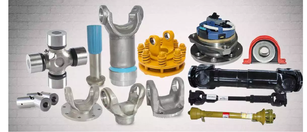
Power Take-Off (PTO) Shafts
Power take-off (PTO) shafts are used on many types of machines, including jet aircraft. They are typically semi-permanently mounted to a marine or industrial engine, and are powered by a drive shaft. The drive shaft also powers secondary implements and accessories. Depending on the application, accessory drives may also be used in aircraft. There are four main types of PTO units used in jet aircraft.
Power take-off (PTO) shaft
 The power take-off (PTO) shaft of a tractor can be controlled to operate in one of two modes: automatic and manual. Automatic mode operates when the PTO shaft starts turning and is automatically engaged when the power lift is raised by actuating the lift lever 9. Manual mode operates when the lift lever is not raised.
The manual mode allows for manual adjustments. A retaining band 12 may be adjusted arcuately about PTO shaft S with an axial center parallel to the axis of the PTO shaft S. The retaining band may be secured by conventional over center clamps. The retaining band 12 may also be adjusted arcuately about pin or bolt 30.
Power take-off (PTO) shaft safety retainers are used to prevent unintended disconnection of the PTO shaft. The safety retainers comprise a stationary openable band that circumscribes the PTO shaft near the connection with driven machinery. The band is preferably offset from the axis of the PTO shaft.
While the PTO shaft is a convenient way to transfer mechanical power to farm implements, there are several inherent hazards associated with using it improperly. Accidental disconnections of the PTO shaft pose a significant risk for the operator. A disconnect can cause the PTO shaft to whip around the driven machinery, potentially causing injury.
Power take-off shaft entanglements can be devastating to the limbs trapped in them, requiring amputation in some cases. In addition to being dangerous, the PTO shafts must be fully guarded to prevent contact with the ground. A farmer must never get too close to an operating PTO shaft to protect their own safety.
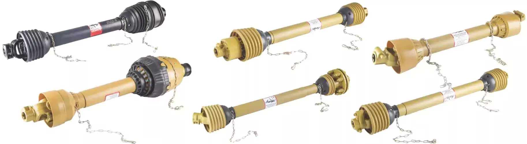
Types
There are several different types of PTO shafts available to suit various applications. They can vary in size and number of splines. Each standard has a specific speed range and is designed to fit a variety of implements. For example, there are German and Italian types of PTO shafts.
The type of PTO shaft you choose will determine the maximum load that can be safely transferred. Depending on the type, the rate at which the PTO clutch engages will be different. For example, a lower-density PTO shaft will engage at a slower rate than a higher-density PTO shaft, while a higher-density shaft will be more tolerant of higher loads.
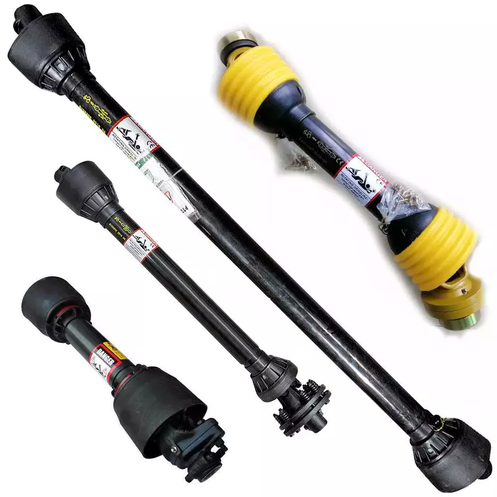
The primary function of a PTO shaft is to secure equipment to the tractor or other agricultural equipment. These parts often feature safety shields on both ends. They are also made in the same shape as the secondary shaft. The front shaft is wider than the secondary shaft, which allows the secondary shaft to fit inside. However, during movement, pieces of the PTO shaft can collapse, making them less safe.
PTO shafts are expensive and easy to steal, so make sure to protect your investment. Make sure the PTO shaft has guards to protect it from thieves. There are two types of PTO shafts: the external and the internal PTO yokes. Internal PTO shafts have an internal PTO yoke, while external PTO shafts use a universal joint. There is also a safety chain and shield on the external PTO shaft.
Depending on the application, you can choose between several different kinds of PTO shafts. Some types of PTO shafts have multiple splines, which can increase the torque transmitted. For applications requiring accuracy and precision, you may want to use a parallel keyed shaft.
Connections
 A PTO shaft has two parts: an input and an output. The input portion of a PTO adapter shaft has a smaller diameter, and the output portion has a larger diameter. Both are connected by splines. These splines have tapered outer ends. The first bore 25 has a first frustoconical wall, while the second bore has a second frustoconical wall.
One of the most common causes of PTO shaft failure is a poorly adjusted clutch. Another common cause is improper lubrication of the PTO shaft’s wide angle joints. PTO shafts should be lubricated at least once every eight hours. If you fail to do this, you risk premature ware and reduced life expectancy.
When a PTO shaft is installed in a tractor, the tractor must be connected to the implement using a coupler frame. The coupler frame has a PTO adapter mounting flange that engages with the PTO stub shaft. The coupler frame can move to accommodate the PTO adapter shaft, and the PTO adapter shaft can pivot and slide with the coupler frame.
When a PTO shaft fails, it can result in damage to the tractor and implement. Identifying the cause will help you fix the problem. Constant compression of the PTO shaft can damage the connecting shafts and connections. This could damage the tractor or implement, resulting in expensive repairs. When this happens, it is important to cut or shorten the shaft to reduce the risk of damage.
PTO shaft 24 extends rearward from tractor 10 and is connected to the front universal joint 28 and first end of variable-length splined drive shaft 32. The shaft is connected to a drive mechanism 36 on a mobile work implement 34. This drive mechanism may be mechanical, hydraulic, or a combination of both.
Safety
It is very important for every person using a tractor to understand the safety of PTO shafts. PTOs can be extremely dangerous, and without the correct shielding, they can cause serious injury. It can also be very dangerous if someone accidentally steps on or falls on one while the machine is operating. This is why it is important for everyone using a tractor to read the manufacturer’s manual and follow the safety guidelines for PTO shafts. Moreover, PTOs must only be used for the purpose intended.
PTO safety should be the number one priority for every operator. A small child was tragically killed when he became entangled with a spinning PTO shaft. His father tried to pull him out of the shaft, but was unable to do so. His clothing, which was near the spinning shaft, caught on the PTO and dragged him into it. His body was thrown around the shaft several times, and he sustained injuries to his leg, right arm, and head.
The PTO shaft is an important part of a tractor, and is used to secure the equipment. It is usually secured by safety shields on both ends. There are several kinds of safety shields. One type is a shield that is attached to the front of the PTO shaft. Another type is a shield that rotates freely on its bearings.
Power takeoffs are common on most small and compact tractors, construction machinery, and other equipment. They rotate to provide the drive for the equipment. However, the PTO shaft is very dangerous because it can easily catch something that gets too close to it. Moreover, loose items can also get tangled around the PTO shaft.
Maintenance
 One of the most important things to do in order to keep your PTO shaft in top condition is to keep it properly greased. This can be done by using a grease gun or a hand pump. It is important to keep the grease fresh and apply it in the appropriate amounts depending on how much you use the PTO. It is also important to separate the primary and secondary shafts and remove any debris from them.
It is also important to check the spline threads on your PTO on a periodic basis. This is important because some signs of dry shafts are not always immediately apparent. Similarly, spline threading and corrosion can occur behind the scenes and go undetected. Proper PTO maintenance is a vital part of safe and efficient operation.
A damaged or worn drive shaft will prevent your car from turning freely, leaving you exposed to higher repair bills. In addition, it will drastically affect the performance of your car. A broken drive shaft can even result in a crash. You should take your vehicle to a mechanic as soon as you notice any of these problems.
Fortunately, most PTO-driven equipment is equipped with a shear pin to prevent collisions and prevent damage to the gearbox and shaft. It should also be replaced regularly to prevent excessive wear. Long bolts pose a risk of entanglement and can easily catch clothing or gloves. For safety reasons, it is important to disengage the PTO when not in use.
Another thing to do is to keep the PTO shields clean. They must be regularly rotated and tested. Always ensure that your drawbar is properly configured for your machine. This prevents stressing or separating the driveline.

editor by czh 2023-01-06
China high quality agriculture machinery mini farm tractor mounted green machine road snow sweepers for sale agricultural parts direct
Equipment Kind: Flooring Sweeper
Relevant Industries: Producing Plant, Machinery Fix Retailers, Farms, House Use, Building functions
Online video outgoing-inspection: Supplied
Equipment Examination Report: Provided
Warranty of core factors: 1 Yr
Main Components: Bearing, Equipment
Condition: New
Gas: Diesel
Use: Snow Clearning, Sweeping highway, P series Heavy Obligation Mixer Hydraulic Geared Motor Planetary Gearbox Velocity Reducer avenue
Cleansing Process: brush
Cleaning Sort: TRACTOR PTO Pushed Clearning
Substance: Metal / Coil
Energy: 20-150hp
Dimension(L*W*H): 1330mm*900mm*1200mm
Guarantee: 1 Yr
Excess weight (KG): 550 kg
Type: Experience-on, mounted with tractors
Item title: tractor mounted street sweeper
Colour: Underneath Client’s Instruction
Purpose: Sweeping snow, street
functioning width: 1500mmm
Composition bodyweight:: 180kgs
Brush material: PP Blended Steel
brush rotation speed: a hundred and eighty rpm
Driveline specification:: Motor/pto drive
Connecting technique with tractor: 3-point suspension
Packaging Particulars: IRON Bundle
Port: HangZhou PORT
Items Description actor highway sweeper: 1. SX Collection Snow Sweeper for tractor is used for sweeping of thin layer of snow, showcased with fast velocity, higher effectiveness andeasy procedure. To distinct away deep snow, it will be far more successful to use it with each other with snow blade. It is also used in sweepingon street and floor.2. SX Series Snow Sweeper for tractor is commonly employed in highway, Custom Substantial Quality Agriculture Equipment Tractor Elements Driveline Cardan Drive PTO Shaft ground, warehouse and so forth, mostly in sweeping of skinny layer of snow,leaves, sand, courtroom and so forth.3.The snow sweeper can be matched to tractor,wheel loader, Stober K514SG3000EK501U Gear Head Velocity Reducers forklift,4.The snow sweeper driven by hydraulic output of these equipment,only tractor could be pushed by PTO.5.PP with metal wires brushes.6.Working width from 1200 to 2500mm7.Suited for cleansing highway,avenue,floor and other flat. Product Technical specs
| Model | SX-150 | SX-one hundred sixty five | SX-a hundred and eighty | SX-210 | ||
| Matching tractor | 20-40hp | 40-60hp | 70-80hp | 85hp-120hp | ||
| Hoisting device | 3-stage | |||||
| Sweeping width (mm) | 1500 | 1650 | 1800 | 2100 | ||
| Brush roller length(mm) | 1740 | 1910 | 2100 | 2450 | ||
| Sweeping thickness(mm) | 0~60 | 0~60 | 0~60 | 0~60 | ||
| Sweeping speed (km/h) | 5~15 | 5~15 | 5~15 | 0~60 | ||
| Brush roller diameter(mm) | 500 | 500 | 500 | 5~15 | ||
| Sweeping angle | 30° | 30° | 30° K37 helical bevel gear motor 3 phase motor pace reducer gearbox large torque pace reducer gearbox | 500 | ||
| Max. transportation height(mm) | 500 | 550 | 600 | 30° | ||
Calculating the Deflection of a Worm Shaft
In this article, we’ll discuss how to calculate the deflection of a worm gear’s worm shaft. We’ll also discuss the characteristics of a worm gear, including its tooth forces. And we’ll cover the important characteristics of a worm gear. Read on to learn more! Here are some things to consider before purchasing a worm gear. We hope you enjoy learning! After reading this article, you’ll be well-equipped to choose a worm gear to match your needs.
Calculation of worm shaft deflection
The main goal of the calculations is to determine the deflection of a worm. Worms are used to turn gears and mechanical devices. This type of transmission uses a worm. The worm diameter and the number of teeth are inputted into the calculation gradually. Then, a table with proper solutions is shown on the screen. After completing the table, you can then move on to the main calculation. You can change the strength parameters as well.
The maximum worm shaft deflection is calculated using the finite element method (FEM). The model has many parameters, including the size of the elements and boundary conditions. The results from these simulations are compared to the corresponding analytical values to calculate the maximum deflection. The result is a table that displays the maximum worm shaft deflection. The tables can be downloaded below. You can also find more information about the different deflection formulas and their applications.
The calculation method used by DIN EN 10084 is based on the hardened cemented worm of 16MnCr5. Then, you can use DIN EN 10084 (CuSn12Ni2-C-GZ) and DIN EN 1982 (CuAl10Fe5Ne5-C-GZ). Then, you can enter the worm face width, either manually or using the auto-suggest option.
Common methods for the calculation of worm shaft deflection provide a good approximation of deflection but do not account for geometric modifications on the worm. While Norgauer’s 2021 approach addresses these issues, it fails to account for the helical winding of the worm teeth and overestimates the stiffening effect of gearing. More sophisticated approaches are required for the efficient design of thin worm shafts.
Worm gears have a low noise and vibration compared to other types of mechanical devices. However, worm gears are often limited by the amount of wear that occurs on the softer worm wheel. Worm shaft deflection is a significant influencing factor for noise and wear. The calculation method for worm gear deflection is available in ISO/TR 14521, DIN 3996, and AGMA 6022.
The worm gear can be designed with a precise transmission ratio. The calculation involves dividing the transmission ratio between more stages in a gearbox. Power transmission input parameters affect the gearing properties, as well as the material of the worm/gear. To achieve a better efficiency, the worm/gear material should match the conditions that are to be experienced. The worm gear can be a self-locking transmission.
The worm gearbox contains several machine elements. The main contributors to the total power loss are the axial loads and bearing losses on the worm shaft. Hence, different bearing configurations are studied. One type includes locating/non-locating bearing arrangements. The other is tapered roller bearings. The worm gear drives are considered when locating versus non-locating bearings. The analysis of worm gear drives is also an investigation of the X-arrangement and four-point contact bearings.
Influence of tooth forces on bending stiffness of a worm gear
The bending stiffness of a worm gear is dependent on tooth forces. Tooth forces increase as the power density increases, but this also leads to increased worm shaft deflection. The resulting deflection can affect efficiency, wear load capacity, and NVH behavior. Continuous improvements in bronze materials, lubricants, and manufacturing quality have enabled worm gear manufacturers to produce increasingly high power densities.
Standardized calculation methods take into account the supporting effect of the toothing on the worm shaft. However, overhung worm gears are not included in the calculation. In addition, the toothing area is not taken into account unless the shaft is designed next to the worm gear. Similarly, the root diameter is treated as the equivalent bending diameter, but this ignores the supporting effect of the worm toothing.
A generalized formula is provided to estimate the STE contribution to vibratory excitation. The results are applicable to any gear with a meshing pattern. It is recommended that engineers test different meshing methods to obtain more accurate results. One way to test tooth-meshing surfaces is to use a finite element stress and mesh subprogram. This software will measure tooth-bending stresses under dynamic loads.
The effect of tooth-brushing and lubricant on bending stiffness can be achieved by increasing the pressure angle of the worm pair. This can reduce tooth bending stresses in the worm gear. A further method is to add a load-loaded tooth-contact analysis (CCTA). This is also used to analyze mismatched ZC1 worm drive. The results obtained with the technique have been widely applied to various types of gearing.
In this study, we found that the ring gear’s bending stiffness is highly influenced by the teeth. The chamfered root of the ring gear is larger than the slot width. Thus, the ring gear’s bending stiffness varies with its tooth width, which increases with the ring wall thickness. Furthermore, a variation in the ring wall thickness of the worm gear causes a greater deviation from the design specification.
To understand the impact of the teeth on the bending stiffness of a worm gear, it is important to know the root shape. Involute teeth are susceptible to bending stress and can break under extreme conditions. A tooth-breakage analysis can control this by determining the root shape and the bending stiffness. The optimization of the root shape directly on the final gear minimizes the bending stress in the involute teeth.
The influence of tooth forces on the bending stiffness of a worm gear was investigated using the CZPT Spiral Bevel Gear Test Facility. In this study, multiple teeth of a spiral bevel pinion were instrumented with strain gages and tested at speeds ranging from static to 14400 RPM. The tests were performed with power levels as high as 540 kW. The results obtained were compared with the analysis of a three-dimensional finite element model.
Characteristics of worm gears
Worm gears are unique types of gears. They feature a variety of characteristics and applications. This article will examine the characteristics and benefits of worm gears. Then, we’ll examine the common applications of worm gears. Let’s take a look! Before we dive in to worm gears, let’s review their capabilities. Hopefully, you’ll see how versatile these gears are.
A worm gear can achieve massive reduction ratios with little effort. By adding circumference to the wheel, the worm can greatly increase its torque and decrease its speed. Conventional gearsets require multiple reductions to achieve the same reduction ratio. Worm gears have fewer moving parts, so there are fewer places for failure. However, they can’t reverse the direction of power. This is because the friction between the worm and wheel makes it impossible to move the worm backwards.
Worm gears are widely used in elevators, hoists, and lifts. They are particularly useful in applications where stopping speed is critical. They can be incorporated with smaller brakes to ensure safety, but shouldn’t be relied upon as a primary braking system. Generally, they are self-locking, so they are a good choice for many applications. They also have many benefits, including increased efficiency and safety.
Worm gears are designed to achieve a specific reduction ratio. They are typically arranged between the input and output shafts of a motor and a load. The two shafts are often positioned at an angle that ensures proper alignment. Worm gear gears have a center spacing of a frame size. The center spacing of the gear and worm shaft determines the axial pitch. For instance, if the gearsets are set at a radial distance, a smaller outer diameter is necessary.
Worm gears’ sliding contact reduces efficiency. But it also ensures quiet operation. The sliding action limits the efficiency of worm gears to 30% to 50%. A few techniques are introduced herein to minimize friction and to produce good entrance and exit gaps. You’ll soon see why they’re such a versatile choice for your needs! So, if you’re considering purchasing a worm gear, make sure you read this article to learn more about its characteristics!
An embodiment of a worm gear is described in FIGS. 19 and 20. An alternate embodiment of the system uses a single motor and a single worm 153. The worm 153 turns a gear which drives an arm 152. The arm 152, in turn, moves the lens/mirr assembly 10 by varying the elevation angle. The motor control unit 114 then tracks the elevation angle of the lens/mirr assembly 10 in relation to the reference position.
The worm wheel and worm are both made of metal. However, the brass worm and wheel are made of brass, which is a yellow metal. Their lubricant selections are more flexible, but they’re limited by additive restrictions due to their yellow metal. Plastic on metal worm gears are generally found in light load applications. The lubricant used depends on the type of plastic, as many types of plastics react to hydrocarbons found in regular lubricant. For this reason, you need a non-reactive lubricant.

China supplier Tder 66kw 74kw 81kw 89kw Mini Agricultural Tractor 4WD Price 60HP 70HP 80HP 90HP 100HP 120HP 4X4 Tractor near me supplier
Product Description
Strong motive power
Adopt Xinchai diesel engine series, large reserves of torque,
low fuel consumption and high economic efficiency.
High reliability
The reinforced PTO structure, large bearing capacity,
meets the requirements of different operation.
Imported high strength powder metallurgic clutch plate,
reliable transmission.
Efficient operation
Adopts 4×(1 + 1) ×2 compound transmission, 8F + 8R
gear, shuttle shift, side control, easy to operate.
Vertical double oil cylinder high pressure lifter, large lifting
force and good operation adaptability.
Optional for creeper gearbox , meets different working
conditions.
Comfortable operation
Hanging flat panel console, reasonable man-machine
engineering.
Full hydraulic steering system, flexible and comfortable
operation.
Optional for cab, comfortable driving space
After sales service
TDER always treat after-sale service more important than sale.
Nowadays more than 30 agents around the world can supply TDER professional after-sale service.
All the product of TDER supplied with one year or 2000 working hours (which occurs first) period quality warranty.
Detail clauses and policies please check our website and product certificate.
FAQ:
1.What Certificate do you have?
TDER workshop meet with the ISO9001:2008 Quality System. .
All of our products with CE certificate. Some of our products meets the EPA requirements.
2.Can you customize and design as the clients’ requirement?
TDER will try its best to meet all kinds of clients’ special requirements.
However, All the customizing and refit should be implemented safely and scientifically.
The colors can be painted as client’s need.
3.How long is the warranty of your products?
Normally 1 year or 2000 working hours whichever occurs first.
Details to see the TDER warranty policy for each model.
4.Can you produce the products labeled with the client’s brand?
With the authorization of the brand, we can OEM for our clients.
5.What payment terms do you accept?
On T/T term 30% down payment is required in advance,and 70% balance shall be settled before shipment.
6.What logistics way we can work for shipment ?
We can ship construction machinery by various transportation tools
1.For 90% of our shipment,we will go by sea,to all main continents such as South America,Middle East,
Africa,Oceania and Europe etc,either by container or Bulk shipment.
2.For neighborhood countries of China,such as Russia,Mongolia, Kazakhstan,Uzbekistan etc., we can ship
trucksby railway.
3.For light spare parts in urgent demand,we can ship it by international courier service,such as DHL,TNT,
UPS,or Fedex.
7.Delivery time:
Standard configuration products are always in stock. The production period of Customizing products is from
7 days to 60 days.
|
Model
|
LTB604
|
LTB704
|
LTB804
|
LTB1004
|
LTB1204
|
|
Drive Type
|
4×4
|
||||
|
Overall Dimension L×W×H (mm)
|
3925×1728×2870
|
4070×1700×2870
|
4130×1720×2820
|
||
|
Overall Dimension with optional driver’s cab L×W×H (mm)
|
3925×1728×2650
|
4070×1700×2650
|
4130×1720×2650
|
||
|
Min. ground clearance (mm)
|
360
|
370
|
|||
|
Min. operating weight (KG)
|
2565
|
2720
|
2950
|
||
|
Gearbox gears number
|
12F+12R
|
||||
|
Forward Speed (Kw/h)
|
2.33-31.04
|
2.33-31.05
|
2.41-31.96
|
2.41-30.91
|
|
|
Reverse Speed (Kw/h)
|
2.04-27.21
|
2.04-27.22
|
2.11-27.14
|
2.11-27.1
|
|
|
Engine Brand
|
XINCHAI
|
QUANCHAI
|
QUANCHAI
|
||
|
Engine Model
|
4D32ZT31/604
|
4D32ZT31/704
|
4C6-80U32
|
4C6-100C35
|
4C6-120C32
|
|
Engine Rated power (Kw)
|
44.1
|
51.5
|
59
|
73.5
|
88.3
|
|
Engine Rated speed (r/min)
|
2400
|
||||
|
Front tires spec.
|
8.3-34
|
9.5-24
|
8.3-34
|
9.5-24
|
|
|
Rear tires spec.
|
11-32
|
14.9-30
|
11-32
|
14.9-30
|
|
|
Max. traction force (KN)
|
13.8
|
14
|
16.6
|
≥25
|
|
|
Fuel Tank Capacity (L)
|
60
|
60
|
60+25
|
||
|
Model
|
LTB604
|
LTB704
|
LTB804
|
LTB1004
|
LTB1204
|
|
Drive Type
|
4×4
|
||||
|
Overall Dimension L×W×H (mm)
|
3925×1728×2870
|
4070×1700×2870
|
4130×1720×2820
|
||
|
Overall Dimension with optional driver’s cab L×W×H (mm)
|
3925×1728×2650
|
4070×1700×2650
|
4130×1720×2650
|
||
|
Min. ground clearance (mm)
|
360
|
370
|
|||
|
Min. operating weight (KG)
|
2565
|
2720
|
2950
|
||
|
Gearbox gears number
|
12F+12R
|
||||
|
Forward Speed (Kw/h)
|
2.33-31.04
|
2.33-31.05
|
2.41-31.96
|
2.41-30.91
|
|
|
Reverse Speed (Kw/h)
|
2.04-27.21
|
2.04-27.22
|
2.11-27.14
|
2.11-27.1
|
|
|
Engine Brand
|
XINCHAI
|
QUANCHAI
|
QUANCHAI
|
||
|
Engine Model
|
4D32ZT31/604
|
4D32ZT31/704
|
4C6-80U32
|
4C6-100C35
|
4C6-120C32
|
|
Engine Rated power (Kw)
|
44.1
|
51.5
|
59
|
73.5
|
88.3
|
|
Engine Rated speed (r/min)
|
2400
|
||||
|
Front tires spec.
|
8.3-34
|
9.5-24
|
8.3-34
|
9.5-24
|
|
|
Rear tires spec.
|
11-32
|
14.9-30
|
11-32
|
14.9-30
|
|
|
Max. traction force (KN)
|
13.8
|
14
|
16.6
|
≥25
|
|
|
Fuel Tank Capacity (L)
|
60
|
60
|
60+25
|
||
Guide to Drive Shafts and U-Joints
If you’re concerned about the performance of your car’s driveshaft, you’re not alone. Many car owners are unaware of the warning signs of a failed driveshaft, but knowing what to look for can help you avoid costly repairs. Here is a brief guide on drive shafts, U-joints and maintenance intervals. Listed below are key points to consider before replacing a vehicle driveshaft.
Symptoms of Driveshaft Failure
Identifying a faulty driveshaft is easy if you’ve ever heard a strange noise from under your car. These sounds are caused by worn U-joints and bearings supporting the drive shaft. When they fail, the drive shafts stop rotating properly, creating a clanking or squeaking sound. When this happens, you may hear noise from the side of the steering wheel or floor.
In addition to noise, a faulty driveshaft can cause your car to swerve in tight corners. It can also lead to suspended bindings that limit overall control. Therefore, you should have these symptoms checked by a mechanic as soon as you notice them. If you notice any of the symptoms above, your next step should be to tow your vehicle to a mechanic. To avoid extra trouble, make sure you’ve taken precautions by checking your car’s oil level.
In addition to these symptoms, you should also look for any noise from the drive shaft. The first thing to look for is the squeak. This was caused by severe damage to the U-joint attached to the drive shaft. In addition to noise, you should also look for rust on the bearing cap seals. In extreme cases, your car can even shudder when accelerating.
Vibration while driving can be an early warning sign of a driveshaft failure. Vibration can be due to worn bushings, stuck sliding yokes, or even springs or bent yokes. Excessive torque can be caused by a worn center bearing or a damaged U-joint. The vehicle may make unusual noises in the chassis system.
If you notice these signs, it’s time to take your car to a mechanic. You should check regularly, especially heavy vehicles. If you’re not sure what’s causing the noise, check your car’s transmission, engine, and rear differential. If you suspect that a driveshaft needs to be replaced, a certified mechanic can replace the driveshaft in your car.
Drive shaft type
Driveshafts are used in many different types of vehicles. These include four-wheel drive, front-engine rear-wheel drive, motorcycles and boats. Each type of drive shaft has its own purpose. Below is an overview of the three most common types of drive shafts:
The driveshaft is a circular, elongated shaft that transmits torque from the engine to the wheels. Drive shafts often contain many joints to compensate for changes in length or angle. Some drive shafts also include connecting shafts and internal constant velocity joints. Some also include torsional dampers, spline joints, and even prismatic joints. The most important thing about the driveshaft is that it plays a vital role in transmitting torque from the engine to the wheels.
The drive shaft needs to be both light and strong to move torque. While steel is the most commonly used material for automotive driveshafts, other materials such as aluminum, composites, and carbon fiber are also commonly used. It all depends on the purpose and size of the vehicle. Precision Manufacturing is a good source for OEM products and OEM driveshafts. So when you’re looking for a new driveshaft, keep these factors in mind when buying.
Cardan joints are another common drive shaft. A universal joint, also known as a U-joint, is a flexible coupling that allows one shaft to drive the other at an angle. This type of drive shaft allows power to be transmitted while the angle of the other shaft is constantly changing. While a gimbal is a good option, it’s not a perfect solution for all applications.
CZPT, Inc. has state-of-the-art machinery to service all types of drive shafts, from small cars to race cars. They serve a variety of needs, including racing, industry and agriculture. Whether you need a new drive shaft or a simple adjustment, the staff at CZPT can meet all your needs. You’ll be back on the road soon!
U-joint
If your car yoke or u-joint shows signs of wear, it’s time to replace them. The easiest way to replace them is to follow the steps below. Use a large flathead screwdriver to test. If you feel any movement, the U-joint is faulty. Also, inspect the bearing caps for damage or rust. If you can’t find the u-joint wrench, try checking with a flashlight.
When inspecting U-joints, make sure they are properly lubricated and lubricated. If the joint is dry or poorly lubricated, it can quickly fail and cause your car to squeak while driving. Another sign that a joint is about to fail is a sudden, excessive whine. Check your u-joints every year or so to make sure they are in proper working order.
Whether your u-joint is sealed or lubricated will depend on the make and model of your vehicle. When your vehicle is off-road, you need to install lubricable U-joints for durability and longevity. A new driveshaft or derailleur will cost more than a U-joint. Also, if you don’t have a good understanding of how to replace them, you may need to do some transmission work on your vehicle.
When replacing the U-joint on the drive shaft, be sure to choose an OEM replacement whenever possible. While you can easily repair or replace the original head, if the u-joint is not lubricated, you may need to replace it. A damaged gimbal joint can cause problems with your car’s transmission or other critical components. Replacing your car’s U-joint early can ensure its long-term performance.
Another option is to use two CV joints on the drive shaft. Using multiple CV joints on the drive shaft helps you in situations where alignment is difficult or operating angles do not match. This type of driveshaft joint is more expensive and complex than a U-joint. The disadvantages of using multiple CV joints are additional length, weight, and reduced operating angle. There are many reasons to use a U-joint on a drive shaft.
maintenance interval
Checking U-joints and slip joints is a critical part of routine maintenance. Most vehicles are equipped with lube fittings on the driveshaft slip joint, which should be checked and lubricated at every oil change. CZPT technicians are well-versed in axles and can easily identify a bad U-joint based on the sound of acceleration or shifting. If not repaired properly, the drive shaft can fall off, requiring expensive repairs.
Oil filters and oil changes are other parts of a vehicle’s mechanical system. To prevent rust, the oil in these parts must be replaced. The same goes for transmission. Your vehicle’s driveshaft should be inspected at least every 60,000 miles. The vehicle’s transmission and clutch should also be checked for wear. Other components that should be checked include PCV valves, oil lines and connections, spark plugs, tire bearings, steering gearboxes and brakes.
If your vehicle has a manual transmission, it is best to have it serviced by CZPT’s East Lexington experts. These services should be performed every two to four years or every 24,000 miles. For best results, refer to the owner’s manual for recommended maintenance intervals. CZPT technicians are experienced in axles and differentials. Regular maintenance of your drivetrain will keep it in good working order.
