Tag Archives: agriculture machine parts

China Auto Spare Parts CV Axle Shaft No. My-A16 Used for 2060 Digging Machine High Quality Gear Axle Joint Drive Shafts Agriculture Drive Shaft pto shaft bush hog

Solution Description

Item Description


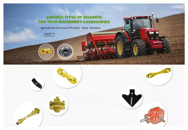
This product is utilized for 2060 CZPT machine . Our innovation delivers increased turning radius and other benefits to the shaft. It has increased efficiency and high quality relying on our exclusive approach items. We take custom-made development and innovation primarily based on drawings and samples.


Organization Profile

HangZhou Minyang Car Elements Production Co., Ltd. – focuses on the OEM production of chassis components of cars, vehicles, agricultural machinery and engineering equipment for a lot more than fifteen years.

FAQ

Q: Which payment terms will you take?

A: We can acknowledge TT, Western union, paypal and funds etc 

Q: When my purchase will be transported?

A:Once we get payment, we will ship your purchase in twenty doing work times.

Q: Which delivery will you supply?

A:By sea, air,  DHL, Fedex, TNT, UPS, EMS, SF 

Q: How long does it get to my deal with?

A:The normal supply time is 20days, relying on which nation you are in.

Q: How can I trace my buy?

A:We will send you the monitoring quantity by electronic mail.

Q: If I am not satisfied with the products, what should I do?

A:You can contact us and inform us about your dilemma. We will provide trade or mend services beneath guarantee.

US $10-999
/ Piece
|
20 Pieces

(Min. Order)

###

Material: 40cr Carbon Steel
Load: Drive Shaft
Stiffness & Flexibility: Stiffness / Rigid Axle
Journal Diameter Dimensional Accuracy: IT6-IT9
Axis Shape: Joint Shaft
Shaft Shape: Spline Shaft

###

Samples:
US$ 50/Piece
1 Piece(Min.Order)

|
Request Sample

###

Customization:

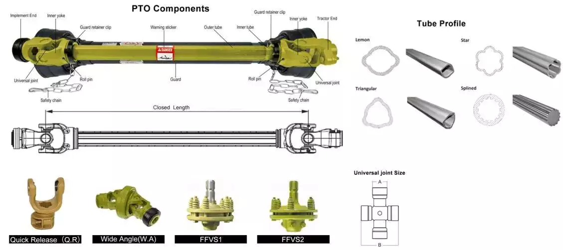
The Different Parts of a PTO Shaft

Power Take-Off (PTO) shafts are an integral part of a tractor’s driveline. Without them, a tractor cannot operate. It is essential to understand the different parts of a PTO shaft, as they are crucial for the operation of your tractor. These parts are typically overlooked during routine tractor maintenance checks, but knowing more about them will help you practice on farm machinery better.

Tractor’s power take-off (PTO) shaft

Shaft CollarA Tractor’s power take-off (or PTO) shaft transfers power from the tractor to an implement. These shafts typically rotate at speeds between 540 and 1000 rpm. A number of safety features help prevent accidental contact between the shaft and the implement.
In order to avoid this problem, tractor operators should be vigilant while operating their tractors. They should make sure that the tractor’s power take-off (PTO) shaft is shielded. These shields include a master shield for the PTO stub, a PTO integral journal shield, and an implement input connection shield. The PTO master shield is mounted on the tractor and extends over the PTO stub on three sides. It is designed to prevent collisions between the tractor and any connected machine drive shaft.
A power take-off (PTO) shaft is an important component on any tractor. It is a shaft that transmits mechanical power from a tractor to an implement or separate machine. Early PTOs used a transmission and were located at the rear of the tractor. They are now available with hydraulic or mechanical drivelines. These power take-offs transfer the tractor’s power to a secondary piece of equipment through a driveshaft.
Proper PTO shaft guards protect people from stepping on rotating shafts. The PTO should not compress fully at any point in the operating range. It should have several inches of overlap at the maximum operating extension. A PTO guard should be positioned properly for each machine.
Despite these benefits, there are still many risks associated with PTO shafts. These powerful and potentially dangerous pieces of machinery can cause severe injury if not used safely. Luckily, proper installation of safety shields can reduce the risk of injury.

Types

PTO shafts come in a variety of different shapes, sizes, and materials. The most common types are square and round, but there are also star-shaped and trilobed types. While the star-shaped type is a typical North American design, the trilobed and lemon-shaped varieties are typically German or Italian. Typically, the lemon-shaped ones are made of an alloy called ‘Lemon Yellow.’ In some cases, the shaft will come with snap rings.
Different manufacturers use various materials for their PTO shafts. The tube of a welded drive shaft must be strong enough to handle the force exerted by the PTO. There are many different materials available, but some are stronger than others. Before choosing the type of drive shaft that is right for your machine, make sure that you know the exact measurements of your driveline.
When deciding between different types of PTO shafts, you must also consider the materials that will be used for your particular application. While splines are the most common material for PTO shafts, you can find various types that have different uses. Carbon steel is malleable and has a low carbon content, which makes it more reliable. A ferrous steel is more durable and contains metals like nickel, chromium, and molybdenum, which make it a great alternative to carbon steel.
A PTO gearbox input shaft extends between the PTO gearbox and the PTO clutch. It is mounted with a toothed wheel 8. An inductive sensor 9 on the shaft outputs a pulsed electronic signal based on the rotational speed of the shaft. These pulsed signals are called inductive speed sensors.

Rotation direction

The PTO shaft is a critical part of the power take-off of a farm tractor. It allows the tractor to transfer power from the engine to an implement such as a mower or other garden equipment. The rotation direction of the PTO shaft depends on the type of implement. Some implements only accept rotation in one direction, while others require rotation in both directions.

Safety chain

Shaft CollarOne of the best ways to protect your PTO shaft is to use a safety chain. A safety chain is a chain that is attached to the PTO shaft, and it prevents the plastic shield from spinning on the shaft. This chain should be fastened to a suitable point on your machine or tractor. It should not be attached to the lower lift arms or the U-guard.
PTO shafts can be very dangerous if they are not guarded. They can rotate as high as 1000 rpm and could seriously injure you. It is also important to ensure that the PTO shaft guard is fitted correctly, and that the tractor is turned off before working on it. In addition, avoiding wearing loose clothing when working around a PTO shaft can help protect your life.
Another way to protect the PTO shaft is to shield the IID shaft. This can be done by using shielding over the straight part of the shaft, the PTO connection, or the Implement Input Connection. A protruding bolt or pin can catch clothing and snag it. If not shielded, the clothing can wrap around the shaft, trapping the person against it.
A good safety chain should be positioned between the tractor and the PTO shaft. The chain should be at least 50 mm wider than the PTO shaft, and should be in good condition. It should cover the entire length of the PTO shaft from the tractor to the first bearing. The PTO shaft must also be fitted with the correct bearing ring. It is also vital to ensure that the PTO guard does not bend or break, as this could result in damage to the PTO shaft.

Shield

Shaft CollarA PTO shaft shield protects the PTO shaft from possible impacts. It is typically made of plastic, but can also be made of metal. These shields are easy to damage, and are therefore preferably made of a durable material. The shields are held in place with brackets. The shields are made with two parts: an inner shield and a protective sleeve.
An improvement to the PTO shaft shield is a bracket that supports both the outer and PTO shaft. It is shown in conjunction with a towed machine in FIGS. 2 and 7. FIG. 7 is a side elevation of the bracket mounted to the tongue of the machine. This shield is designed to prevent the PTO shaft from becoming damaged during the towed process.
The main risk associated with PTO mishaps is entanglement, which can result in serious injuries. If a shaft separates from a tractor, it can strike nearby workers or people. Proper maintenance can minimize the risk of entanglement and save lives. Thankfully, equipment manufacturers have made huge strides in reducing the risk of these accidents. Operators should always make sure that the PTO shaft shield is in place to avoid the risk of entanglement.
In addition to preventing entanglement, a PTO shaft shield also helps protect the universal joints that are mounted on the PTO shaft. The shield is made of plastic or steel. It is typically shaped like an inverted U and covers both the top and sides of the shaft. A detachable PTO shaft shield is also available.
As with all parts of a PTO driveline, the PTO shaft shield should be maintained to prevent damage to the bearings. It is necessary to inspect the shield and replace it whenever it becomes damaged. PTO equipment is often used outdoors, and it is frequently exposed to crop debris, rust, and dirt that can affect the bearings. Proper maintenance will extend the equipment’s lifespan and reduce maintenance costs.
China Auto Spare Parts CV Axle Shaft No. My-A16 Used for 2060 Digging Machine High Quality Gear Axle Joint Drive Shafts Agriculture Drive Shaft     pto shaft bush hogChina Auto Spare Parts CV Axle Shaft No. My-A16 Used for 2060 Digging Machine High Quality Gear Axle Joint Drive Shafts Agriculture Drive Shaft     pto shaft bush hog
editor by czh 2022-12-13

China high quality agriculture machinery mini farm tractor mounted green machine road snow sweepers for sale agricultural parts direct

Equipment Kind: Flooring Sweeper
Relevant Industries: Producing Plant, Machinery Fix Retailers, Farms, House Use, Building functions
Online video outgoing-inspection: Supplied
Equipment Examination Report: Provided
Warranty of core factors: 1 Yr
Main Components: Bearing, Equipment
Condition: New
Gas: Diesel
Use: Snow Clearning, Sweeping highway, P series Heavy Obligation Mixer Hydraulic Geared Motor Planetary Gearbox Velocity Reducer avenue
Cleansing Process: brush
Cleaning Sort: TRACTOR PTO Pushed Clearning
Substance: Metal / Coil
Energy: 20-150hp
Dimension(L*W*H): 1330mm*900mm*1200mm
Guarantee: 1 Yr
Excess weight (KG): 550 kg
Type: Experience-on, mounted with tractors
Item title: tractor mounted street sweeper
Colour: Underneath Client’s Instruction
Purpose: Sweeping snow, street
functioning width: 1500mmm
Composition bodyweight:: 180kgs
Brush material: PP Blended Steel
brush rotation speed: a hundred and eighty rpm
Driveline specification:: Motor/pto drive
Connecting technique with tractor: 3-point suspension
Packaging Particulars: IRON Bundle
Port: HangZhou PORT

Items Description actor highway sweeper: 1. SX Collection Snow Sweeper for tractor is used for sweeping of thin layer of snow, showcased with fast velocity, higher effectiveness andeasy procedure. To distinct away deep snow, it will be far more successful to use it with each other with snow blade. It is also used in sweepingon street and floor.2. SX Series Snow Sweeper for tractor is commonly employed in highway, Custom Substantial Quality Agriculture Equipment Tractor Elements Driveline Cardan Drive PTO Shaft ground, warehouse and so forth, mostly in sweeping of skinny layer of snow,leaves, sand, courtroom and so forth.3.The snow sweeper can be matched to tractor,wheel loader, Stober K514SG3000EK501U Gear Head Velocity Reducers forklift,4.The snow sweeper driven by hydraulic output of these equipment,only tractor could be pushed by PTO.5.PP with metal wires brushes.6.Working width from 1200 to 2500mm7.Suited for cleansing highway,avenue,floor and other flat. Product Technical specs

ModelSX-150SX-one hundred sixty fiveSX-a hundred and eightySX-210
Matching tractor20-40hp40-60hp70-80hp 85hp-120hp
Hoisting device3-stage
Sweeping width (mm)1500165018002100
Brush roller length(mm)1740191021002450
Sweeping thickness(mm)0~600~600~600~60
Sweeping speed (km/h)5~155~155~150~60
Brush roller diameter(mm)5005005005~15
Sweeping angle30°30°30° K37 helical bevel gear motor 3 phase motor pace reducer gearbox large torque pace reducer gearbox 500
Max. transportation height(mm)50055060030°
Particulars Photographs Organization Profile Advise Items

Calculating the Deflection of a Worm Shaft

In this article, we’ll discuss how to calculate the deflection of a worm gear’s worm shaft. We’ll also discuss the characteristics of a worm gear, including its tooth forces. And we’ll cover the important characteristics of a worm gear. Read on to learn more! Here are some things to consider before purchasing a worm gear. We hope you enjoy learning! After reading this article, you’ll be well-equipped to choose a worm gear to match your needs.
worm shaft

Calculation of worm shaft deflection

The main goal of the calculations is to determine the deflection of a worm. Worms are used to turn gears and mechanical devices. This type of transmission uses a worm. The worm diameter and the number of teeth are inputted into the calculation gradually. Then, a table with proper solutions is shown on the screen. After completing the table, you can then move on to the main calculation. You can change the strength parameters as well.
The maximum worm shaft deflection is calculated using the finite element method (FEM). The model has many parameters, including the size of the elements and boundary conditions. The results from these simulations are compared to the corresponding analytical values to calculate the maximum deflection. The result is a table that displays the maximum worm shaft deflection. The tables can be downloaded below. You can also find more information about the different deflection formulas and their applications.
The calculation method used by DIN EN 10084 is based on the hardened cemented worm of 16MnCr5. Then, you can use DIN EN 10084 (CuSn12Ni2-C-GZ) and DIN EN 1982 (CuAl10Fe5Ne5-C-GZ). Then, you can enter the worm face width, either manually or using the auto-suggest option.
Common methods for the calculation of worm shaft deflection provide a good approximation of deflection but do not account for geometric modifications on the worm. While Norgauer’s 2021 approach addresses these issues, it fails to account for the helical winding of the worm teeth and overestimates the stiffening effect of gearing. More sophisticated approaches are required for the efficient design of thin worm shafts.
Worm gears have a low noise and vibration compared to other types of mechanical devices. However, worm gears are often limited by the amount of wear that occurs on the softer worm wheel. Worm shaft deflection is a significant influencing factor for noise and wear. The calculation method for worm gear deflection is available in ISO/TR 14521, DIN 3996, and AGMA 6022.
The worm gear can be designed with a precise transmission ratio. The calculation involves dividing the transmission ratio between more stages in a gearbox. Power transmission input parameters affect the gearing properties, as well as the material of the worm/gear. To achieve a better efficiency, the worm/gear material should match the conditions that are to be experienced. The worm gear can be a self-locking transmission.
The worm gearbox contains several machine elements. The main contributors to the total power loss are the axial loads and bearing losses on the worm shaft. Hence, different bearing configurations are studied. One type includes locating/non-locating bearing arrangements. The other is tapered roller bearings. The worm gear drives are considered when locating versus non-locating bearings. The analysis of worm gear drives is also an investigation of the X-arrangement and four-point contact bearings.
worm shaft

Influence of tooth forces on bending stiffness of a worm gear

The bending stiffness of a worm gear is dependent on tooth forces. Tooth forces increase as the power density increases, but this also leads to increased worm shaft deflection. The resulting deflection can affect efficiency, wear load capacity, and NVH behavior. Continuous improvements in bronze materials, lubricants, and manufacturing quality have enabled worm gear manufacturers to produce increasingly high power densities.
Standardized calculation methods take into account the supporting effect of the toothing on the worm shaft. However, overhung worm gears are not included in the calculation. In addition, the toothing area is not taken into account unless the shaft is designed next to the worm gear. Similarly, the root diameter is treated as the equivalent bending diameter, but this ignores the supporting effect of the worm toothing.
A generalized formula is provided to estimate the STE contribution to vibratory excitation. The results are applicable to any gear with a meshing pattern. It is recommended that engineers test different meshing methods to obtain more accurate results. One way to test tooth-meshing surfaces is to use a finite element stress and mesh subprogram. This software will measure tooth-bending stresses under dynamic loads.
The effect of tooth-brushing and lubricant on bending stiffness can be achieved by increasing the pressure angle of the worm pair. This can reduce tooth bending stresses in the worm gear. A further method is to add a load-loaded tooth-contact analysis (CCTA). This is also used to analyze mismatched ZC1 worm drive. The results obtained with the technique have been widely applied to various types of gearing.
In this study, we found that the ring gear’s bending stiffness is highly influenced by the teeth. The chamfered root of the ring gear is larger than the slot width. Thus, the ring gear’s bending stiffness varies with its tooth width, which increases with the ring wall thickness. Furthermore, a variation in the ring wall thickness of the worm gear causes a greater deviation from the design specification.
To understand the impact of the teeth on the bending stiffness of a worm gear, it is important to know the root shape. Involute teeth are susceptible to bending stress and can break under extreme conditions. A tooth-breakage analysis can control this by determining the root shape and the bending stiffness. The optimization of the root shape directly on the final gear minimizes the bending stress in the involute teeth.
The influence of tooth forces on the bending stiffness of a worm gear was investigated using the CZPT Spiral Bevel Gear Test Facility. In this study, multiple teeth of a spiral bevel pinion were instrumented with strain gages and tested at speeds ranging from static to 14400 RPM. The tests were performed with power levels as high as 540 kW. The results obtained were compared with the analysis of a three-dimensional finite element model.
worm shaft

Characteristics of worm gears

Worm gears are unique types of gears. They feature a variety of characteristics and applications. This article will examine the characteristics and benefits of worm gears. Then, we’ll examine the common applications of worm gears. Let’s take a look! Before we dive in to worm gears, let’s review their capabilities. Hopefully, you’ll see how versatile these gears are.
A worm gear can achieve massive reduction ratios with little effort. By adding circumference to the wheel, the worm can greatly increase its torque and decrease its speed. Conventional gearsets require multiple reductions to achieve the same reduction ratio. Worm gears have fewer moving parts, so there are fewer places for failure. However, they can’t reverse the direction of power. This is because the friction between the worm and wheel makes it impossible to move the worm backwards.
Worm gears are widely used in elevators, hoists, and lifts. They are particularly useful in applications where stopping speed is critical. They can be incorporated with smaller brakes to ensure safety, but shouldn’t be relied upon as a primary braking system. Generally, they are self-locking, so they are a good choice for many applications. They also have many benefits, including increased efficiency and safety.
Worm gears are designed to achieve a specific reduction ratio. They are typically arranged between the input and output shafts of a motor and a load. The two shafts are often positioned at an angle that ensures proper alignment. Worm gear gears have a center spacing of a frame size. The center spacing of the gear and worm shaft determines the axial pitch. For instance, if the gearsets are set at a radial distance, a smaller outer diameter is necessary.
Worm gears’ sliding contact reduces efficiency. But it also ensures quiet operation. The sliding action limits the efficiency of worm gears to 30% to 50%. A few techniques are introduced herein to minimize friction and to produce good entrance and exit gaps. You’ll soon see why they’re such a versatile choice for your needs! So, if you’re considering purchasing a worm gear, make sure you read this article to learn more about its characteristics!
An embodiment of a worm gear is described in FIGS. 19 and 20. An alternate embodiment of the system uses a single motor and a single worm 153. The worm 153 turns a gear which drives an arm 152. The arm 152, in turn, moves the lens/mirr assembly 10 by varying the elevation angle. The motor control unit 114 then tracks the elevation angle of the lens/mirr assembly 10 in relation to the reference position.
The worm wheel and worm are both made of metal. However, the brass worm and wheel are made of brass, which is a yellow metal. Their lubricant selections are more flexible, but they’re limited by additive restrictions due to their yellow metal. Plastic on metal worm gears are generally found in light load applications. The lubricant used depends on the type of plastic, as many types of plastics react to hydrocarbons found in regular lubricant. For this reason, you need a non-reactive lubricant.

China high quality agriculture machinery mini farm tractor mounted green machine road snow sweepers for sale     agricultural parts direct